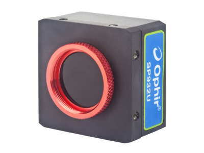
SP932U Beam Profiling Camera

SP932U Beam Profiling Camera

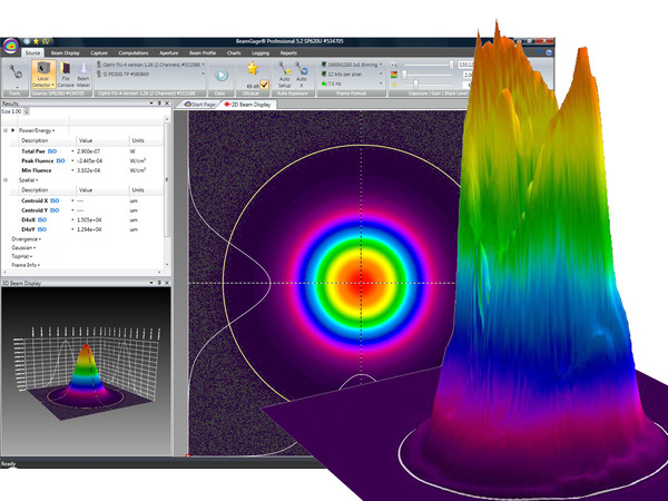
USB 3.0 Silicon CMOS High Resolution Camera with BeamGage
 
Description: 

USB 3.0 Global Shutter CMOS, high resolution Camera, with improved accuracy, especially at popular NIR and Nd:YAG wavelengths with BeamGage new "Blooming Correction" Algorithm. Compact, square design to increase setup versatility

  • 2048 x 1536 pixel resolu tion with a 3.45 µm pixel pitch
  • 24 fps at full resolution
  • New "Blooming Correction" algorithm at NIR and no smearing
  • BeamGage Standard or Professional software included
  • Requires Win 10, 64 bit or higher

Specification

  • 190-1100nm
  • 34.5μm 5.3mm
  • USB 3.0
  • Silicon CMOS
  • CW, Pulsed
  • 7.06mm x 5.3mm
  • 2048 x 1536
  • 3.45μm x 3.45μm
  • 72 dB
  • 24fps
  • CE, UKCA, China RoHS
Need help finding the right beam profiler? Try our Beam Profiler Finder

Ordering

  • BGS-USB3-SP932U

    SP90606

    BeamGage Standard software, software license, 1/1.8" format 2048 x 1536 pixel camera with 4.5mm C mount CCD recess. Comes with USB 3.0 cable, Trigger Cable and 3 ND filters

    Request a Quote
  • BGP-USB3-SP932U

    SP90607

    BeamGage Professional software, software license, 1/1.8" format 2048 x 1536 pixel camera with 4.5mm C mount CCD recess. Comes with USB 3.0 cable, Trigger Cable and 3 ND filters

    Request a Quote
  • BGS TO BGP UPGRADE

    SP90233

    Upgrade BeamGage Standard Edition to Professional Edition. Requires a new camera key to activate.

    Request a Quote
  • Firmware update for SP932U cameras

    MKS Ophir is obligated to constantly improve the quality and accuracy of their products. Run the firmware update utility to improve beam profiling accuracy on SP932U cameras.
    (The update utility requires BeamGage v6.18 or later to be installed. Utility must be run for all SP932U cameras, connecting one at a time.)

    To download the update utility press here

  • BeamGage StandardBeamGage Standard
    BeamGage Standard is our full-function software with an extensive set of ISO quantitative measurement, our patented Ultracal™ algorithm for the highest accuracy measurements in the industry.
  • BeamGage ProfessionalBeamGage Professional
    BeamGage Professional has all of the functionality that BeamGage Standard includes. BeamGage Professional supports all of our beam profiling cameras, includes window partitioning to allow analysis of multiple beams on a single camera, and includes an automation interface written in .NET to push data to your custom applications.

Drawings

FAQ

What is the advantage of the SP932U camera?

CMOS sensor used in the SP932U camera has an advantage over CCD Ophir cameras due to the possibility of faster measurement speed and lack of Smearing Effect.

Was this FAQ helpful to you? yes no
Close

Why SP932U camera is the most suitable for NIR wavelengths beam profiling?

SP932U exploits a special mathematical algorithm to remove the "Blooming Effect" at 1000-1100nm.
Each camera is specially calibrated to remove the blooming and provide precise beam profiling measurement at popular NIR and Nd: YAG ranges.

Was this FAQ helpful to you? yes no
Close

Videos

Video Series: BeamGage Tutorials Video Series: BeamGage Tutorials
Fundamentals of Laser Measurement & Beam Profiling Fundamentals of Laser Measurement & Beam Profiling Fundamentals of Laser Measurement & Beam Profiling

Is your laser's beam profile shaped correctly for your application?
This video teaches the fundamentals of laser beam profiles and discusses the benefits of profiling your laser beam.
Several case studies are presented showing before and after laser beam profiles.

Measuring Laser Focus Spot Size in an industrial Medical Device Application Measuring Laser Focus Spot Size in an industrial Medical Device Application Measuring Laser Focus Spot Size in an industrial Medical Device Application

This step-by-step tutorial will show you how to set up a camera-based beam profiling system on an industrial single-pulse laser welding system.
It will also demonstrate for you how to simultaneously analyze the laser's focused spot, measure the laser's energy per pulse, and measure its temporal pulse shape.

How to Design Your Perfect Laser Beam with BeamMaker How to Design Your Perfect Laser Beam with BeamMaker How to Design Your Perfect Laser Beam with BeamMaker

BeamMaker helps engineers, technicians, and researchers understand a beam's modal content by subtracting theoretically generated modes from real beam measurement data. Derive a perfect beam profile by specifying the mode, size, width, height, intensity, angle, and noise content - then comparing it to theoretically derived measurements. The end result is knowledge about how much the real beam varies from the desired beam.

Watch the BeamGage Tutuorials, including tips on handling your CCD camera, software install, introduction to the BeamGage user interface, the context-sensitive help system and user manual, customizing your reporting environment, and configuring BeamGage to display specific laser measurements.

Support

Tutorials and Articles

White Paper – Apples to Apples: Which Camera Technologies Work Best for Beam Profiling Applications, Part 1

In 1997, Dr. Carlos Roundy, founder and president of Spiricon Inc., presented a paper at the 4th International Workshop on Lasers and Optics Characterization in Munich Germany. This paper was based on work that was carried out at Spiricon in the mid 90’s. At the time new insights were being presented on how to characterize a laser beam. Previous definitions were somewhat simplistic and most often were driven by customers telling us how they wanted the beam measured. Read more...

Ensuring Quality Welds in Medical Devices

Many customers involved with laser welding measure the pulse energy output of their lasers, but is this all the data required needed to ensure quality welds? Steve Schellenberg at Spinal Modulation had his doubts. While he found pulse energy measurement using his Ophir equipment useful in qualifying his laser welding process, two of his laser welding stations were producing different quality welds despite producing identical laser pulse energies. One laser welder seemed to be doing an OK job, while the other welder produced significantly lower quality welds. Steve suspected differing laser Read more...

Why is Test Equipment Always Suspect?

When a laser malfunctions and diagnostics begin, why is test equipment the first to be questioned for its accuracy when it was the laser that failed first ? Read more...

White Paper – ISO compliance of non-contact, real-time beam analysis

Here we show that non-contact beam profiling based on Rayleigh scattering fully complies with the ISO11146 standard Read more...

Imaging UV light with CCD Cameras

Is it possible to image a UV laser with a Silicon Sensor CCD camera offered by Ophir-Spiricon? The answer is yes, but the direct UV light ablates Silicon CCD chips over time. The ablation is cumulative and depends on the intensity, the wavelength, and the duration of the light on the sensor. The best choice for imaging UV light without damage is to avoid directly imaging the beam on the CCD sensor by using an UV image converter... Read more...

Understanding Dynamic Range…The Numbers Game

There is a fair amount of confusion caused by the reporting of dynamic range of beam profilers. The purpose of this applications note is to explain some of the terminology used in the discussion of this parameter by both Ophir- Spiricon and other suppliers of beam profilers. DefinitionDynamic Range is the ratio of the largest measurable signal to the smallest measurable signal. The smallest measurable signal is typically defined as that equal to the noise level, or alternatively the “Noise Equivalent Exposure” or that point where the Signal-to-noise ratio (SNR) is 1. To Read more...

The Focal Length Divergence Measurement Method

The Focal Length Divergence measurement method is based upon the beam width of a focused beam’s spot size and the focal length of the focusing optic. The Focal Length Divergence method provides a means for finding the far-field beam divergence at any point in the beam propagation path. As shown below, the calculation performed by the BeamGage® software is quite simple; however the optical setup must be done with great care. Read more...

Laser Beam Measurement Vocabulary

Wavelength: In physics, the wavelength of a sinusoidal wave is the spatial period of the wave— the distance over which the wave's shape repeats,[1] and the inverse of the spatial frequency. It is usually determined by considering the distance between consecutive corresponding points of the same phase, such as crests, troughs, or zero crossings and is a characteristic of both traveling waves and standing waves, as well as other spatial wave patterns.[2][3] Wavelength is commonly designated by the Greek letter lambda (λ)... Read more...

White Paper – Beam Width Measurement Accuracy

Introduction Read more...

White Paper – Apples to Apples: Which Camera Technologies Work Best for Beam Profiling Applications, Part 2: Baseline Methods and Mode Effects

By G.E. Slobodzian, Director of Engineering, Retired, Ophir-Spiricon Read more...

BeamGage Profiling with .Net Automation Interface and LabVIEW®

BeamGage Professional and BeamGage Enterprise version 5.7 are supported with Automation via .Net components. Both include a LabVIEW example that can be run with the LabVIEW Run-Time Engine that is provided with the BeamGage software CD or available for free download from National Instruments. Read more...

Medical lasers: When the laser application requires utmost safety

The continuous development of laser technology has revolutionized many areas of our lives in the past decades. The most direct influence on the individual is thanks to advancements in laser technology for medical or cosmetic applications. If you want to ensure optimal results, you have to know – and measure – critical laser parameters. Read more...

Accessories

Customers that purchase the above items also consider the following items:
  • Optical Camera Trigger
    The Optical Camera Trigger is an optical sensor that detects pulsed light sources and generates outputs to trigger a camera. The front aperture of the Optical Trigger must be directed at a light source that provides the necessary properties for trigger activation. (e.g. a laser flash lamp, a pick-off source from the main laser beam, or similar).
  • LBS-300 Attenuator
    The LBS-300s beam splitter attachment for C-mount, CS-mount, or Ophir mount cameras allow you to measure laser beams with diameters up to 15mm and powers ranging from 10mW to ~400W(1). The beam sampler is designed so that the preferential polarization selection effect of a single wedge is cancelled out and the resulting beam image is polarization
  • CCTV Lens
    When direct imaging in front of the camera, like imaging an image projected onto a defusing surface, like a ground glass plate, it is necessary to reduce the image so that it completely fits onto the CCD chip surface. The 25mm and 50mm CCTV lenses image an object from a given plane in front of the lens onto the CCD while reducing the size.
  • Near field profiling can also be used with camera profilers to analyze small beams, and involves a microscope objective lens to image the beam onto a camera detector array. This technique expands the measurement range of the camera to include smaller beams, which could not be ordinarily measured due to the pixel size of the detector array. Near
  • 4X Beam Reducer
    The 4X Beam Reducer is an imaging system that images the plane 30cm in front of the reducer onto the camera CCD sensor while reducing the size 4 times and inverting it. The beam reducer uses the 3 screw on attenuators provided with the camera. Since the intensity of a beam after reduction will be increased by 4x4=16 times.
  • 4X UV Image Reducing Converter
    The UV image converters are fluorescent plates that convert UV radiation that is poorly imaged by silicon cameras into visible light that is then imaged onto the CCD of the camera. These fluorescent plates are specially designed for UV conversion and have a high light output, wide linear dynamic range and high damage threshold.
  • 4X Beam Expander
    Beam expanders are designed to work with C-mount threaded cameras that have 4.5mm imager back focal spacing or with CS (12.5mm) back focal spacing. The 4X beam expander is an expanding telescope that images the beam as it looks at 8mm from the end of the expander onto the CCD while enlarging the image 4X.
  • Microscope Objectives
    Microscope objectives are available for expanding the beam even more. There are objectives for 6X, 12X, and 22X expansion. The various expanders allow the use of our 2% and 10% filters as well as the variable attenuator so as to accommodate the camera to a wide range of source intensities.
  • Stackable Prism Front-Surface Beam Samplers
    The Prism Front-Surface Beam Sampler (PFSA) is a C-mount fixture housing a UV-Grade Fused Silica right angle prism, used for sampling the front surface reflection for high power/energy beam-profiling applications. Reflection at nominal incidence of 45°is polarization and wavelength dependent, with 532nm s-polarization reflected at 8.27%, and p
  • Stackable Beam Splitters
    The stackable beam splitters are designed for maximum modularity and shortest beam path. They are compatible with almost all of our cameras having the standard C mount thread and can mount either to other attenuators or to the camera itself.
  • Beam Tap I & II
    Laser beam attenuation while reducing polarization with broadband and YAG wavelength beam sampling.
  • UV-VIS-NIR (350-1100nm) Wavelengths Attenuation by accompanied ND filters (ND1 and ND3) Operates with Ophir standard SP932U camera (purchased separately)