FPS-1
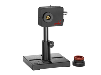
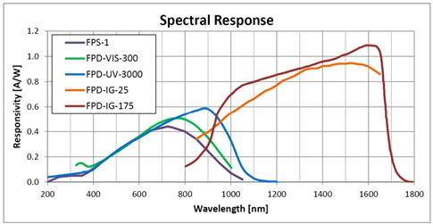
Der FPS-1 ist ein schneller optischer Detektor zur Visualisierung und Messung der temporalen Charakteristiken von Laserstrahlen im Spektralbereich von 193 bis 1100nm. Er arbeitet mit einer UV-erweiterten Silizium PIN-Photodiode und ist dafür ausgelegt, optische in elektrische Signale zu wandeln, die dann mit einem zusätzlichen Messgerät wie einem Oszilloskop oder einem Spektralanalysator gemessen werden. Der FPS-1 hat eine Anstiegszeit von 1,5 nsec. Seine Vorspannung wird entweder durch interne Batterien oder eine externe Gleichstromversorgung (enthalten) erzeugt.
Specification
- UV-Si
- 1.5 nsec
- 193-1100 nm
- 1.02 mm
- 0.05 pW/√Hz
- 49 L x 61 W x 27 D (mm)
- 0.8 mm²
- 720 nm
- 0.45 A/W
- 0.18 V/(W/cm²)
- 12 VDC
- External or Batteries
- 233 MHz
- 0.3nA typ, 1.0nA max
- 3 mW
- 1/4-20
- BNC
- SM-1
- CE, UKCA, China RoHS
Catalog & Manuals
FAQ
Do I need to recalibrate my instrument?
What kind of measurements can I do with a temporal detector? Why are they important?
With a temporal detector you can measure the rise time, fall time, pulse duration and pulse frequency. Many laser applications use pulsed laser, for example medical lasers, LIDARs, and high power fiber laser for metal processing to name a few. The parameters of the laser pulses are critical for the performance of the application.
CloseThe temporal sensor can provide accurate measurement of temporal parameters. How can I relate those to absolute value of pulse energy?
Pulse energy can be measured directly using one of Ophir's calibrated energy sensors. Another way is to use a calibrated power sensor and calculate the pulse energy using:
Pulse energy [J] = average power [W] / pulse rate [pulses per second]
Temporal sensors provide a signal that is proportional to the instantaneous power output of the laser. When viewing the pulse waveform on an oscilloscope, the integrated area under the curve is proportional to the total pulse energy.
CloseWhat is the difference between calibrated power sensors such as PD300 and temporal sensors?
Calibrated power sensorsmeasure the average power of CW and pulsed laser beams. The sensor is connected to an Ophir Meter or PC Interface. Power sensors are optimized for low noise and linear response in order to maximize power measurement accuracy. The measured laser beam must be smaller than the sensor's aperture in order to obtain an accurate power measurement. Temporal sensors are optimized for high speed response in order to reproduce pulse temporal characteristics with high fidelity. A temporal sensor is usually smaller than the laser beam size and samples a portion of the beam. The temporal sensor is connected to a scope or spectrum analyzer to display temporal characteristics of pulsed lasers.
CloseI need to measure the temporal pulse shape of a very powerful laser. How can I do that without damaging the detector?
There are several possible ways to do this:
- Use a beam sampling optic (partially reflective mirror or uncoated window).
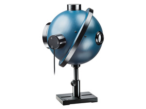
- Feed the laser beam into an integrating sphere and attach the temporal detector to the sphere using the adapter accessory.
- Use a beam dump and position the detector such that it picks up some of the reflected laser radiation.
Attenuating accessories are available (see temporal detector's product page). Laser power density on the attenuators should be less than 50 W/cm².
CloseI don’t see my signal on the oscilloscope or the signal is not as expected. What should I do?
I sometimes need to see an analog representation of my laser power on a scope, in parallel to measuring it with a thermal sensor. What solutions are available?
There are a number of options, depending on the purpose.
- In many cases, the simplest solution could be to make use of the analog output of the meter – that gives a voltage signal proportional to the actual reading (it is in fact just a D/A translation of what is being displayed), so it represents a fully calibrated reading. The full scale value is a function of the meter being used and the power range it is on.
- The "SH to BNC connector" (Ophir P/N 7Z11010) simply takes the raw output from the detector element and sends it to the scope. It bypasses the sensor's EEROM which contains the calibration data, so it essentially turns the sensor into an uncalibrated "dumb" analog sensor. It should be noted, though, that in some cases we could be talking about a signal to the scope that may be low, perhaps even near the noise level of the scope, which limits the usefulness of this method at low powers.
- If the need is to see the pulse width – the temporal profile – the solution (assuming applicable specs) is to use an approprinte temporal sensor connected to a scope; you can point it anywhere where it will catch some backscatter from your laser, and you'll see the pulse temporal form as it really is.
In the specifications of the “Pulse Characterization Sensors”, Noise Equivalent Power is specified in units of “√Hz”. What does that mean”
Admittedly a unit such as “√ Hz” is not very intuitive. In general: Noise Equivalent Power (NEP) is defined as the signal power that gives a signal-to-noise ratio of 1 in a one-hertz output bandwidth. Taking the bandwidth of the measurement into account is where the “square root of Hz” comes in. The noise spectrum typically has a relatively flat response, and the noise level changes with the square root of the frequency range; for example, if the frequency range doubles, the noise component increases by √2 (1.414). In detector datasheets, the bandwidth is typically normalized to 1 Hz (which is usually far below the detection bandwidth), to allow detectors with different bandwidth specifications to be directly compared.
CloseCalibration
Ophir's temporal sensors do not require calibration.
Videos
Using these Ophir fast photodetectors, you can see and measure the temporal characteristics of pulsed and CW laser beams.
Tutorials
Pulse Power Measurement: Measuring Instantaneous Power of a Short Pulse
Ophir Power/Energy Meter Calibration Procedure and Traceability/Error Analysis
This document discusses the interpretation and basis for stated measurement accuracy of Ophir Laser Power/Energy meters.
1. General Discussion
2. Combination of Errors and Total Error
3. Analysis of Power and Energy Calibration Errors
4. Detailed Analysis of Power and Energy Calibration Errors
Effect of Ambient Conditions on Laser Measurements
We are often asked about the specified ranges of various ambient conditions (temperature, humidity, etc.) for Ophir instruments. In this article we will clarify the effects of these conditions on laser measurements, so you’ll be able to use your Ophir laser measurement instrument effectively.
 Weiterlesen...How to Properly Select a Laser Power or Energy Sensor
The selection of a sensor to accurately measure the power of a laser or energy of a pulsed laser can seem like a simple and easy procedure. However, many times the selection process is limited to choosing a sensor that only meets the range of power or energy to be measured, leaving out several other essential criteria of the laser specifications; that without their consideration, can allow the wrong sensor to be selected, the laser to be measured inaccurately and likely to cause the sensor to fail prematurely.
Watch Our Laser Measurement Video
 Weiterlesen...Laser Measurements in Materials Processing: How and When They Absolutely, Positively Must Be Made
5 Situations Where Laser Performance Measurement is Necessary
Specification
- UV-Si
- 1.5 nsec
- 193-1100 nm
- 1.02 mm
- 0.05 pW/√Hz
- 49 L x 61 W x 27 D (mm)
- 0.8 mm²
- 720 nm
- 0.45 A/W
- 0.18 V/(W/cm²)
- 12 VDC
- External or Batteries
- 233 MHz
- 0.3nA typ, 1.0nA max
- 3 mW
- 1/4-20
- BNC
- SM-1
- CE, UKCA, China RoHS
Accessories
-
ND1 Attenuator
7Z08200ND1 nom. X10 attenuator
-
ND2 Attenuator
7Z08201ND2 nom. X50 attenuator
-
1" Port to SM1 adapter
7Z082891" integrating sphere port to SM-1 thread adapter for mounting the FPS-1 on IS6 integrating spheres.
-
FC Fiber Adapter
7Z08229This fiber adapter is used for connecting power and energy sensors to a standard FC-type fiber. Many sensors need an additional mounting bracket to connect to all fiber adapters. More information can be found in the datasheet below. -
ST Fiber Adapter
7Z08226This fiber adapter is used for connecting power and energy sensors to a standard ST-type fiber. Many sensors need an additional mounting bracket to connect to all fiber adapters. More information can be found in the datasheet below. -
SC Fiber Adapter
7Z08227This fiber adapter is used for connecting power and energy sensors to a standard SC-type fiber. Many sensors need an additional mounting bracket to connect to all fiber adapters. More information can be found in the datasheet below. -
SMA Fiber Adapter
1G01236AThis fiber adapter is used for connecting power and energy sensors to a standard SMA-type fiber. Many sensors need an additional mounting bracket to connect to all fiber adapters. More information can be found in the datasheet below. -
PD300R/FPS-1 Fiber Bracket
1G02259A mounting bracket is needed to connect round photodiode sensors to a fiber adapter (SC, ST, FC or SMA). This bracket can be used for the PD300R (round) photodiode series, as well as the FPS-1 fast photodiode. It is not needed for the PD300-IRG sensor. This bracket is also used for mounting ND attenuators on the FPS-1. -
Female SM1 to SM1 Adapter
1G02260For mounting to SM1 optical components and systems