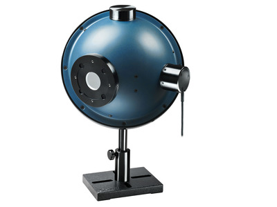
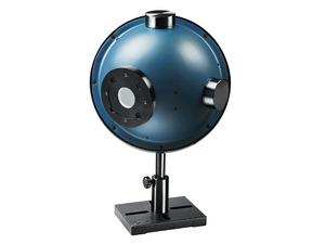
Specification
Catalog & Manuals
FAQ
There are several models of IS6 integrating sphere detectors. how can I select the right one?
Integrating spheres are used when you have divergent light sources. How do they work?
Integrating Sphere Theory
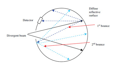
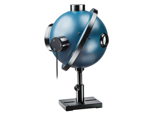
Integrating spheres are used when we have divergent light sources. As shown in the illustration, an integrating sphere has its inner surface coated with a surface that highly reflects (typically 99%) in a scattering, nonspecular way. Thus when a divergent beam hits the walls of the integrating sphere, the light is reflected and scattered many times until the light hitting any place on the walls of the sphere has the same intensity.
A detector placed in the sphere thus gets the same intensity as anywhere else and the power the detector detects is thus proportional to the total incident power independent of the beam divergence. (The detector is so arranged that it only sees scattered light and not the incident beam). An ideal integrating sphere has a surface with reflective properties are Lambertian. This means that light incident on the surface is scattered uniformly in all directions in the 2pi steradians solid angle above the surface. The surface used by Ophir closely approximates a Lambertian surface.
3A-IS Series
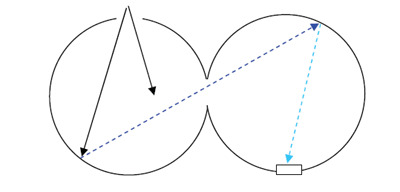
The 3A-IS series has two 50mm integrating spheres in series with a photodiode detector. The two series spheres scramble up the light very well thus giving output very independent of incident beam divergence angle. The two spheres in series also insure that the light hitting the detector is greatly reduced in intensity thus allowing use up to 3 Watts even though photodiodes saturate at about 1mW. There are two models, the 3A-IS with a silicon photodiode for 400 – 1100nm and the 3A-ISIRG with an InGaAs detector for 800 – 1700nm
Are there any special problems with the calibration stability of integrating sphere sensors?
The Ophir integrating sphere sensors, models 3A-IS and 3A-IS-IRG have a white diffuse reflecting coating on the inside of the integrating sphere. The sensitivity of the sensor is quite sensitive to the reflectivity of the coating. If the coating absorption goes up 1%, it can cause a 5% change in reading. Therefore, care must be taken not to soil or damage the white coating of the sensors. Also it may be a good idea to send the sensors for recalibration yearly.
CloseWhen using the fiber optic adaptor, how do we handle power loss due to the fiber relative to calibration?
All Ophir power meters, including photodiode power meters, have an air gap between the fiber tip and the sensor. Therefore they measure the power emitted by the fiber into the air and do not take into account any reflection losses there are in the fiber. Therefore, if in actual use, the fiber will be coupled with no loss to another element, then the losses should be added to the reading. These losses are usually about 4%. Thus if the reading on the Ophir meter is say 100mW, then in lossless use, the real power will be 104mW.
CloseDo I need to recalibrate my instrument? How often must it be recalibrated?
Among the Integrating Sphere accessories offered, there are “Port Plugs” (white), and “Port Covers” (black). What’s the difference?
An unused port should be closed, to prevent unwanted light from entering the sphere. Closing it with a diffuse white port plug, however, adds the surface area of that plug to the (diffuse white) effective area of the sphere that is doing the “integrating”. For a calibrated integrating sphere sensor, this change in the behavior of the sphere changes its calibration, and results in incorrect readings. In such applications, a black “Port Cover” should be used.
CloseThe IS6 integrating spheres have a specified “Sensitivity to beam size” and “Sensitivity to beam divergence”. What is that?
In general, as the divergence angle of the beam entering the integrating sphere increases - and as its diameter increases – the assumptions on which we base the sphere’s performance (infinite reflections inside the sphere walls, perfectly uniform distribution of light inside the sphere, etc.) become less correct. We therefore specify the maximum beam divergence (such as ± 60⁰), and we also state the maximum possible change in reading caused by change in beam size. In fact, we also state in the data sheet that the maximum additional uncertainty due to beam size is only ±1% for beam divergence < 30⁰, and ±3% for beam divergence > 30⁰. To give this more meaning: Basically, if you measure the power using a beam that is a few mm in diameter, that has a relatively small divergence angle, and is centered on the sphere’s input port aperture, you can safely ignore this additional uncertainty.
CloseI need to measure the power of a diverging beam whose divergence is very asymmetrical; the Fast axis divergence is ± 80 degrees, while the Slow axis divergence is ± 20 degrees. Will the IS6-D integrating sphere work? It’s specified Maximum Beam Divergence is ± 60 degrees.
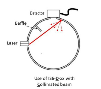
Can I use my IS6-D Integrating Sphere (which is normally used for measuring Divergent beams) to measure a Collimated beam? I know that normally one would use an IS6-C for Collimated beams, but can I manage with my -D sphere on a 1-time basis?
Here is a trick that would make this possible:
The beam should be aimed so that it is incident close to the detector port (but not hitting the baffle) – as shown in this drawing:
This way the "first bounce" will be directed to the opposite side of the sphere, ensuring that the detector will in fact see only light from the "second bounce" and onward, i.e. light that has been uniformly distributed around the inner sphere surface (normally, light from the "first bounce" of a collimated beam is not yet uniformly distributed and we don’t want the detector to see it – that is the main idea behind the different C and D configurations. This trick gets around that).
CloseVideos

When you measure a beam coming out of a fiber, there are some parameters that have a different meaning than they do when referring to "regular" beam measurements. This video clarifies some issues you'll need to keep in mind.

Measuring the emitted power of an LED can be tricky; it is different in some important ways from measuring the power of a laser beam. This video shows you how to use the Ophir 3A-IS Integrating Sphere Sensor, along with the Auxiliary LED accessory, to easily make accurate measurements in LED applications.

When a power/energy meter is in "Calibrate" mode, various "Factors" are displayed to the user. This video explains the meaning of each of these factors.
If your application requires measurement of a widely diverging beam, an integrating sphere might be the right solution.
Learn what Integrating Spheres are, what they help you do, and see the range of solutions available.
Tutorials
Integrating Sphere Fundamentals and Applications
Measuring Power of Divergent Beams with Integrating Sphere Sensors
An integrating sphere is used to measure a divergent light source. As shown in the illustration, an integrating sphere has its inner surface coated with a surface that highly reflects (typically 99%) in a scattering, nonspecular way. Thus when a divergent beam hits the walls of the integrating sphere, the light is reflected and scattered many times until the light hitting any place on the walls of the sphere has the same intensity.
 阅读更多...White Paper – Measuring LED Power and Irradiance with Calibrated Photodiodes
In many industries LEDs are replacing traditional broadband light sources such as mercury, deuterium, Xenon, and quartz-halogen lamps. Systems and applications transitioning to LEDs are reengineered in terms of optics, electronics, heat management and more. Similarly, the equipment used by professionals to measure the output of these sources needs to be fitted for measuring LEDs.
 阅读更多...Ophir Power/Energy Meter Calibration Procedure and Traceability/Error Analysis
This document discusses the interpretation and basis for stated measurement accuracy of Ophir Laser Power/Energy meters.
1. General Discussion
2. Combination of Errors and Total Error
3. Analysis of Power and Energy Calibration Errors
4. Detailed Analysis of Power and Energy Calibration Errors
VCSEL Measurement Solutions
Laser Measurements in Materials Processing: How and When They Absolutely, Positively Must Be Made
How do I know what range, or scale, to set my power/energy meter to? And what happens if I go over range?
Each given range represents one level of gain of an internal amplifier. The electronics, as always, have a limited Dynamic Range. If the measured signal is too low, in other words near the bottom of the range, then it may be lost in the noise and the reading will be inaccurate and noisy. If it’s too high – there may be saturation issues. To give an instrument a usefully wide dynamic range, multiple scales or ranges are used. Switching from range to range can be automatic (“Autorange”), or manual. Autoranging simply starts automatically at the least sensitive range and works its way down the ranges, sampling the signal as it goes, till it finds a range at which the signal is properly detected. Note, by the way, that only in POWER mode is Autoranging available. If we are working in Single Shot Energy mode, there is no Autoranging – simply because when we are measuring a single pulse, the instrument has no opportunity to work its way down the ranges as in Power mode.
 阅读更多...White Paper – Low Frequency Power Mode
Types of power / Energy Laser Sensors General Introduction
Power and Single Shot Energy Sensors
Ophir provides two types of power sensors: Photodiode sensors and Thermal sensors. Photodiode sensors are used for low powers from picowatts up to hundreds of milliwatts and as high as 3W. Thermal sensors are for use from fractions of a milliwatt up to thousands of watts.
Thermal sensors can also measure single shot energy at pulse rates not exceeding one pulse every ~5s.
Repetitive Pulse Energy Sensors
For higher pulse rates, Ophir has pyroelectric energy sensors able to measure pulse rates up to tens of KHz. These are described in the energy sensor section, section 1.3.
Measuring Average Power of Pulsed Lasers with Photodiodes
5 Situations Where Laser Performance Measurement is Necessary
Specification
- Ø26mm
- 700-1800nm
- 20μW-30W
- Ø154 (mm)
- 0.3mJ
- 1kW/cm²
- N.A.
- 30W
- ±60 deg
- N.A.
- ±3%
- CE, UKCA, China RoHS
Accessories
See specification sheet for details on which accessories are supplied with sphere.
-
IS-2.5” Port plug
7Z08283AWhite reflectance material Ø63.5mm plug
-
IS-1” Port plug
7Z08280AWhite reflectance material Ø25.4mm plug
-
IS-2.5” Port cover
7Z08281AMatt black coated Ø63.5mm cover
-
IS-1” Port cover
7Z08282AMatt black coated Ø25.4mm cover
-
2.5" to 1" port reducer
7Z08305ATo convert the 2.5” port into a 1” port PTFE
-
1” FC fiber adapter
7Z08286Attaches to the 1” port for FC fiber input/output
-
FPD to IS6 Adapter
7Z08350For mounting FPD sensor series (except FPS-1) to North Pole post of IS6 series
-
1" Port to SM1 adapter
7Z082891" integrating sphere port to SM-1 thread adapter for mounting the FPS-1 on IS6 integrating spheres.
-
1” SMA fiber adapter
7Z08285Attaches to the 1” port for SMA fiber input/output
-
Set of aperture masks
7Z08307Ø5, Ø 7, Ø10mm apertures, for use with 2.5” to 1” port reducer P/N 7Z08305A
-
Flange attachment
7Z08306Dovetail flange for use with 2.5” to 1” port reducer P/N 7Z08305A