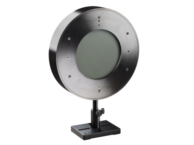
L100(500)A-PF-120
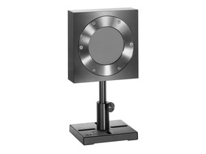
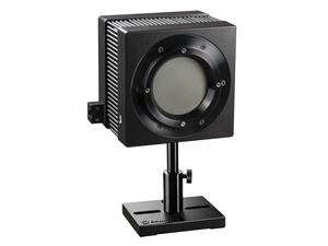
The L100(500)A-PF-120 is a convection or conduction cooled thermal power/energy laser measurement sensor with the very large aperture of 120mm.
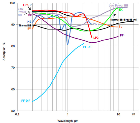
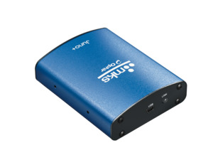
It can measure power from 1W to 500W and energy from 6J to 6000J. It has the PF volume absorber and covers the spectral range from 0.15 to 20µm. The sensor comes with a standard 1.5 meter cable for connecting to a meter or PC interface.
Specification
- PF volume absorber
- Ø120mm
- 0.15-20µm
- 1W-500W
- 6J-6000J
- Ø200 W x 35 D (mm)
- 6000J
- 2kW/cm²
- 7 s
- 1.5J/cm²
- 15J/cm²
- 500W
- CE, UKCA, China RoHS
Catalog & Manuals
FAQ
How should I clean my sensor?
First, clean the absorber surface with a tissue, using Umicore #2 Substrate Cleaner, acetone or methanol. Then dry the surface with another tissue. Please note that a few absorbers (Pyro-BB, 10K-W, 15K-W, 16K-W and 30K-W) cannot be cleaned with this method. Instead, simply blow off the dust with clean air or nitrogen. Don't touch these absorbers. Also, HE sensors (such as the 30(150)A-HE-17) should not be cleaned with acetone.
Note: These suggestions are made without guarantee. The cleaning process may result in scratching or staining of the surface in some cases and may also change the calibration.
Must I use a particular sensor only with the meter it was ordered with?
Ophir meters and sensors are calibrated independently. Each meter has the same sensitivity as the other within about 2 tenths of a percent. Each sensor is calibrated independently of a particular meter with its calibration information contained in the DB15 plug. When the sensor is connected to the meter, the meter reads and interprets this information. Since the accuracy of our sensors is typically +/-3%, the extra 0.2% error that could come from plugging into a different meter is negligible and therefore it does not matter which calibrated meter we use with a particular calibrated sensor.
CloseWhen an accuracy spec is given, what exactly is meant?
The Ophir specification on accuracy is in general 2 sigma standard deviation. This means, for instance, that if we list the accuracy as +/-3%, this means that 95% of the sensors will be within this accuracy and 99% will be within +/-4%. For further information on accuracy see https://www.ophiropt.com/laser-measurement-instruments/laser-power-energy-meters/tutorial/calibration-procedure and https://www.ophiropt.com/laser--measurement/knowledge-center?search=calibration&=SEARCH
CloseHow do you calculate the power and energy density of a laser beam?
If the power is P and the diameter of the beam is D then the power density is P /(.785 * D2) . If it is a pulsed laser and the energy is E, the repetition rate is R and the diameter is D then the power density is E*R/(.785 * D2), The energy density is E/(.785 * D2). The sensor finder will automatically calculate the power and energy density.
CloseHow can I measure the energy of short pulses on a thermal detector when its response time is as slow as several seconds?
The thermal sensor works by measuring the heat flowing through its sensor. When measuring a short pulse, the heat is absorbed in the sensor absorber and then flows out through the sensing elements. The integral of this heat flow is a measure of the energy. Thus the sensor is actually measuring the energy that flows after the pulse is finished and the pulse width does not matter for this measurement.
CloseDoes the damage threshold depend on power level?
The damage threshold of thermal sensors does depend on the power level and not only the power density because the sensor disc itself gets hotter at high powers. For instance, the damage threshold of the Ophir broadband coating may be 50KW/cm2 at 10 Watts but only 10KW/cm2 at 300W. The Ophir specifications for damage threshold are always given for the highest power of use of a particular sensor, something which is not done by most other manufacturers. This should be taken into account when comparing specifications. The Sensor Finder takes the power level into consideration when calculating damage threshold.
Watch the 'FAQ: Does damage threshold depend on power level?' video
Do I need to recalibrate my instrument? How often must it be recalibrated?
Can a laser measurement depend on the distance from the laser to the sensor?
In theory, if a beam is completely parallel and fits within the aperture of a sensor, then it should make no difference at all what the distance is; it will be the same number of photons (ignoring absorption by the air, which is negligible except in the UV below 250nm). If, nevertheless, you do see such a distance dependence, there could be one of the following effects happening:
- If you are using a thermal type power sensor, you might actually be measuring heat from the laser itself; when very close to the laser, the thermal sensor might be “feeling” the laser’s own heat. That would not, however, continue to have an effect at more than a few cm distance unless the light source is weak and the heat source is strong.
- Beam geometry – The beam may not be parallel and may be diverging. Often, the lower intensity wings of the beam have greater divergence rate than the main portion of the beam. These may be missing the sensor's aperture as the distance increases. To check that you'd need to use a profiler, or perhaps a BeamTrack PPS (Power/Position/Size) sensor.
- If you are measuring pulse energies with a diffuser-based pyroelectric sensor: Some users find that when they start with the sensor right up close to the laser and move it away, the readings drop sharply (typically by some 6%) over the first few cm. This is likely caused by multiple reflections between the diffuser and the laser device, which at the closest distance might be causing an incorrectly high reading. You should back off from the source by at least some 5cm, more if the beam is not too divergent.
Needless to say, it’s also important to be sure to have a steady setup; a sensor held by hand could easily be moved around involuntarily, which could cause partial or complete missing of the sensor’s aperture at increasing distance, particularly for an invisible beam.
CloseHow is the performance of thermal sensors affected by ambient temperature?
Water cooled sensors will hardly be affected by ambient temperature since the sensor temperature is determined by the water temperature.
Ophir convection and fan cooled sensors are designed to operate in an ambient environment of 25degC up to the maximum rated power continuously.
When operating at its maximum rated power, the sensor’s body should typically not exceed about 80degC in temperature.
Note: If the room temperature is higher than 25degC, then the maximum power (at which the sensor can be safely operated) should be derated accordingly from the specified maximum (since dissipation of the heat from inside the sensor to the surrounding air will be more difficult). For example, if the room temperature is 35degC, then the maximum power limit should be (80-35)/(80-25) = 82% of maximum rated power as given in the sensor’s spec.
Videos

In this short “Basics” video we review in general how one goes about measuring laser beam power, so that you’ll have a clear basic understanding of what the different sensor types are, and when you would use which type.

A pulsed laser could have an average power of, say, 1 Watt, yet a peak power of 1 Megawatt – so when specifying it’s rather important to understand the difference! In this video you will learn what exactly these 2 concepts mean. You’ll also learn how to measure Peak Power, which can sometimes be tricky.
Calculate theoretical peak power with the peak power calculator
In this short “Basics” video we review the use – and selection - of thermal sensors for measuring low, medium and high laser powers.
Tutorials
Laser Power Sensors introduction
As described in the general introduction, the thermopile sensor has a series of bimetallic junctions. A temperature difference between any two junctions causes a voltage to be formed between the two junctions. Since the junctions are in series and the «hot» junctions are always on the inner, hotter side, and the «cold» junctions are on the outer, cooler side, radial heat flow on the disc causes a voltage proportional to the power input. Laser power impinges on the center of the thermopile sensor disk (on the reverse side of the thermopile), flows radially and is cooled on the periphery. The array of thermocouples measures the temperature gradient, which is proportional to the incident or absorbed power. In principle, the reading is not dependent on the ambient temperature since only the temperature difference affects the voltage generated and the voltage difference depends only on the heat flow, not on the ambient temperature.
 Read more...Common Reasons for Thermal Sensor Damage or Out of Tolerance Conditions
This document was created to assist our valued customers in the proper care and maintenance of Ophir thermal laser power sensors. The following information is for reference only. If you have any reason to believe that the sensor is no longer performing within the original specifications,we always recommend that you send it in for repair and/or recalibration by our trained technicians to bring the unit back to the proper NIST traceable standards. We believe that Ophir thermal sensors can be used for many years without any repairs when used with the proper laser optical setup. We hope that this document will enable you to also enjoy the long life and reliable results for which Ophir-Spiricon is known.
 Read more...How to Properly Select a Laser Power or Energy Sensor
The selection of a sensor to accurately measure the power of a laser or energy of a pulsed laser can seem like a simple and easy procedure. However, many times the selection process is limited to choosing a sensor that only meets the range of power or energy to be measured, leaving out several other essential criteria of the laser specifications; that without their consideration, can allow the wrong sensor to be selected, the laser to be measured inaccurately and likely to cause the sensor to fail prematurely.
Watch Our Laser Measurement Video
 Read more...Calibration Accuracy of Ophir’s High Power Sensors
An explanation of how we do this is provided below (A). In addition, a recent check of Ophir’s 5000W head by PTB in Germany shows excellent agreement between our calibration and their standards. The details of the correspondence between our sensor and their standard at powers up to 1400W is included here (B).
A. High Power Measurement Calibration Method and Estimated Accuracy of Models 5000W and 10K-W
How Much of the Power Sensor Aperture Can My Laser Fill Up?
The entire aperture senses power, so you can use the whole head. That said, a beam in the inner 50% of the surface area (about 70% of the diameter) is specified by Ophir to be uniform within +/-2%. The sensitivity around the edges might be a little less, but generally the sensitivity doesn’t vary by more than +/-2% over the entire aperture.
 Read more...Effect of Ambient Conditions on Laser Measurements
We are often asked about the specified ranges of various ambient conditions (temperature, humidity, etc.) for Ophir instruments. In this article we will clarify the effects of these conditions on laser measurements, so you’ll be able to use your Ophir laser measurement instrument effectively.
 Read more...Ophir Power/Energy Meter Calibration Procedure and Traceability/Error Analysis
This document discusses the interpretation and basis for stated measurement accuracy of Ophir Laser Power/Energy meters.
1. General Discussion
2. Combination of Errors and Total Error
3. Analysis of Power and Energy Calibration Errors
4. Detailed Analysis of Power and Energy Calibration Errors
Laser Measurements in Materials Processing: How and When They Absolutely, Positively Must Be Made
How do I know what range, or scale, to set my power/energy meter to? And what happens if I go over range?
Each given range represents one level of gain of an internal amplifier. The electronics, as always, have a limited Dynamic Range. If the measured signal is too low, in other words near the bottom of the range, then it may be lost in the noise and the reading will be inaccurate and noisy. If it’s too high – there may be saturation issues. To give an instrument a usefully wide dynamic range, multiple scales or ranges are used. Switching from range to range can be automatic (“Autorange”), or manual. Autoranging simply starts automatically at the least sensitive range and works its way down the ranges, sampling the signal as it goes, till it finds a range at which the signal is properly detected. Note, by the way, that only in POWER mode is Autoranging available. If we are working in Single Shot Energy mode, there is no Autoranging – simply because when we are measuring a single pulse, the instrument has no opportunity to work its way down the ranges as in Power mode.
 Read more...Types of power / Energy Laser Sensors General Introduction
Power and Single Shot Energy Sensors
Ophir provides two types of power sensors: Photodiode sensors and Thermal sensors. Photodiode sensors are used for low powers from picowatts up to hundreds of milliwatts and as high as 3W. Thermal sensors are for use from fractions of a milliwatt up to thousands of watts.
Thermal sensors can also measure single shot energy at pulse rates not exceeding one pulse every ~5s.
Repetitive Pulse Energy Sensors
For higher pulse rates, Ophir has pyroelectric energy sensors able to measure pulse rates up to tens of KHz. These are described in the energy sensor section, section 1.3.
Lasers and Solar Cell Manufacturing, Scribing of Photovoltaic Materials
5 Situations Where Laser Performance Measurement is Necessary
Specification
- PF volume absorber
- Ø120mm
- 0.15-20µm
- 1W-500W
- 6J-6000J
- Ø200 W x 35 D (mm)
- 6000J
- 2kW/cm²
- 7 s
- 1.5J/cm²
- 15J/cm²
- 500W
- CE, UKCA, China RoHS
Accessories
-
3m Cable
7E01122A* Order only with purchase of a sensor.
3m cable to connect sensor to power meter or interface. Order along with sensor to receive this instead of the standard 1.5m cable. -
5m Cable
7E01122B* Order only with purchase of a sensor.
5m cable to connect sensor to power meter or interface. Order along with sensor to receive this instead of the standard 1.5m cable. -
10m Cable
7E01122C* Order only with purchase of a sensor.
10m cable to connect sensor to power meter or interface. Order along with sensor to receive this instead of the standard 1.5m cable. -
12m Cable
7E01122D* Order only with purchase of a sensor.
12m cable to connect sensor to power meter or interface. Order along with sensor to receive this instead of the standard 1.5m cable. -
SH to BNC Adapter
7Z11010Allows connection of smart sensors to voltage measuring device for measurement of raw voltage output