PD300-IRG
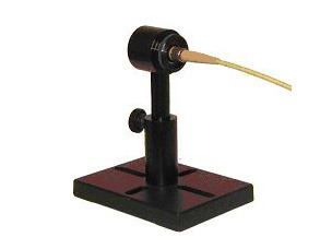
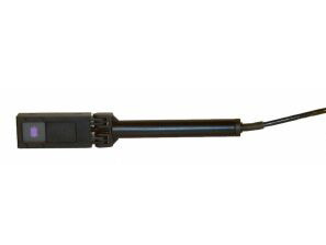
The PD300-IRG is a sensitive photodiode laser measurement sensor for telecom applications. It can accept either fiber input or free space with 5mm aperture. It has a removable filter. Without filter, its spectral range is 800 - 1700nm and its power measuring range is 10pW - 800µW. With filter the spectral range is 950 - 1700nm and the power range is 20µW - 150mW. The sensor comes with a 1.5 meter cable for connecting to a meter or PC interface.
Specification
- N.A.
- Ø5mm (max)
- 800-1700nm
- 10pW-200mW
- N.A.
- N.A.
- Ø30 W x 29 D (mm)
- 100μJ
- 5W/cm²
- 0.2 s
- N.A.
- N.A.
- 200mW
- N.A.
- CE, UKCA, China RoHS
Catalog & Manuals
FAQ
The total error when using a PD-300 head is listed as +/- 3%. Is that 3% of the reading or 3% of the total range?
When using the fiber optic adaptor, how do we handle power loss due to the fiber relative to calibration?
All Ophir power meters, including photodiode power meters, have an air gap between the fiber tip and the sensor. Therefore they measure the power emitted by the fiber into the air and do not take into account any reflection losses there are in the fiber. Therefore, if in actual use, the fiber will be coupled with no loss to another element, then the losses should be added to the reading. These losses are usually about 4%. Thus if the reading on the Ophir meter is say 100mW, then in lossless use, the real power will be 104mW.
CloseCan the PD300 be used with the filter in and with fiber adapter at the same time?
When measuring a fiber output, should I put the fiber tip right up against the PD300 detector? If not, how close should I come?
The PD300 sensors are not designed to measure with the fiber pushed up right against the detector surface. It may be reading lower in such a case due to saturation of the detector from the concentrated beam or higher due to back reflections off the detector and back again from the fiber tip. The optimal reading will be where the beam is expanded to a size of 2-5mm diameter. Therefore, you should back off the fiber to a distance where the beam has expanded somewhat. Do not back off too far, otherwise if the nominal beam size is larger than given above, you may lose some of the beam off the edges of the detector.
CloseDo I need to recalibrate my instrument? How often must it be recalibrated?
Can I use a PD300 photodiode sensor to measure power of a scanned beam?
For measuring power of a scanned beam we recommend using the BC20, and not the PD300. Since a scanned beam will spend only a fraction of the time of each scan on the detector, the average power measured by the detector will correspondingly be only a fraction of the actual power of the beam. The BC20 is specially designed for such applications by having a peak-hold circuit integrated in its electronics.
CloseCan I use a PD300 sensor inside a thermal chamber, in which the temperature cycles beyond the recommended operating temperature range?
It should be okay, as long as:
- the wavelength is not near the long wavelength limit where the PD300 has a large temperature dependence;
- there is no condensation on the window of the detector which could interfere with the beam and affect the reading.
We suggest the customer does an experiment with a stable laser source (such as a pointer laser) shining in through a window onto the detector while the unit is temperature cycled to see if the reading changes. The final measurement should be back at the original temperature so as to make sure the laser hasn’t changed.
CloseWhy do Photodiode-based power sensors like the PD300 have a specified “Max pulse energy”?
Although these sensors measure average power (of both CW and repetitively pulsed beams), not pulse energy, it is possible for a pulsed beam to have average power within the sensor’s rated limits and yet have the energy of the pulses themselves be high enough to cause a momentary saturation of the sensor. It is important to be sure that pulse energy is also within sensor spec – not just the average power. This is explained in detail in this White Paper.
CloseCalibration
Videos

When using a photodiode laser power sensor to measure very low power pulsed beams (nW to mW), there are some issues you need to be aware of. This video shows you how to avoid some common problems and ensure maximum accuracy.

Optical measurements in telecom applications have unique challenges. This video will introduce you to the solutions Ophir offers to help you.
In this short “Basics” video, we review in general the use of photodiode sensors for measuring very low laser powers.
Tutorials
Laser Power Sensors introduction
As described in the general introduction, the thermopile sensor has a series of bimetallic junctions. A temperature difference between any two junctions causes a voltage to be formed between the two junctions. Since the junctions are in series and the «hot» junctions are always on the inner, hotter side, and the «cold» junctions are on the outer, cooler side, radial heat flow on the disc causes a voltage proportional to the power input. Laser power impinges on the center of the thermopile sensor disk (on the reverse side of the thermopile), flows radially and is cooled on the periphery. The array of thermocouples measures the temperature gradient, which is proportional to the incident or absorbed power. In principle, the reading is not dependent on the ambient temperature since only the temperature difference affects the voltage generated and the voltage difference depends only on the heat flow, not on the ambient temperature.
 Read more...Common Reasons for Photodiode Sensor Damage or Out of Tolerance Conditions
We have included this document with your recent calibration order because we have noticed an out of tolerance condition obtained from your equipment when returned for calibration. This document was created to assist our valued customers in the proper care and maintenance of Ophir photodiode sensors. The following information is for reference only. If you have any reason to believe that the sensor is no longer performing within the original specifications, we always recommend that you send it in for repair and/or recalibration by our trained technicians to bring the unit back to the proper NIST traceable standards.
Ophir photodiode sensors can be used for many years without any repairs when used with the proper laser optical setup. Many of our customers have sensors that are using their original absorber that are over ten years of age. We hope that this document will enable you to also enjoy the long life and reliable results that Ophir- Spiricon is known for.
 Read more...How to Properly Select a Laser Power or Energy Sensor
The selection of a sensor to accurately measure the power of a laser or energy of a pulsed laser can seem like a simple and easy procedure. However, many times the selection process is limited to choosing a sensor that only meets the range of power or energy to be measured, leaving out several other essential criteria of the laser specifications; that without their consideration, can allow the wrong sensor to be selected, the laser to be measured inaccurately and likely to cause the sensor to fail prematurely.
Watch Our Laser Measurement Video
 Read more...Effect of Ambient Conditions on Laser Measurements
We are often asked about the specified ranges of various ambient conditions (temperature, humidity, etc.) for Ophir instruments. In this article we will clarify the effects of these conditions on laser measurements, so you’ll be able to use your Ophir laser measurement instrument effectively.
 Read more...Ophir Power/Energy Meter Calibration Procedure and Traceability/Error Analysis
This document discusses the interpretation and basis for stated measurement accuracy of Ophir Laser Power/Energy meters.
1. General Discussion
2. Combination of Errors and Total Error
3. Analysis of Power and Energy Calibration Errors
4. Detailed Analysis of Power and Energy Calibration Errors
Laser Measurements in Materials Processing: How and When They Absolutely, Positively Must Be Made
How do I know what range, or scale, to set my power/energy meter to? And what happens if I go over range?
Each given range represents one level of gain of an internal amplifier. The electronics, as always, have a limited Dynamic Range. If the measured signal is too low, in other words near the bottom of the range, then it may be lost in the noise and the reading will be inaccurate and noisy. If it’s too high – there may be saturation issues. To give an instrument a usefully wide dynamic range, multiple scales or ranges are used. Switching from range to range can be automatic (“Autorange”), or manual. Autoranging simply starts automatically at the least sensitive range and works its way down the ranges, sampling the signal as it goes, till it finds a range at which the signal is properly detected. Note, by the way, that only in POWER mode is Autoranging available. If we are working in Single Shot Energy mode, there is no Autoranging – simply because when we are measuring a single pulse, the instrument has no opportunity to work its way down the ranges as in Power mode.
 Read more...White Paper – Low Frequency Power Mode
Types of power / Energy Laser Sensors General Introduction
Power and Single Shot Energy Sensors
Ophir provides two types of power sensors: Photodiode sensors and Thermal sensors. Photodiode sensors are used for low powers from picowatts up to hundreds of milliwatts and as high as 3W. Thermal sensors are for use from fractions of a milliwatt up to thousands of watts.
Thermal sensors can also measure single shot energy at pulse rates not exceeding one pulse every ~5s.
Repetitive Pulse Energy Sensors
For higher pulse rates, Ophir has pyroelectric energy sensors able to measure pulse rates up to tens of KHz. These are described in the energy sensor section, section 1.3.
Measuring Average Power of Pulsed Lasers with Photodiodes
5 Situations Where Laser Performance Measurement is Necessary
Specification
- N.A.
- Ø5mm (max)
- 800-1700nm
- 10pW-200mW
- N.A.
- N.A.
- Ø30 W x 29 D (mm)
- 100μJ
- 5W/cm²
- 0.2 s
- N.A.
- N.A.
- 200mW
- N.A.
- CE, UKCA, China RoHS
Accessories
-
PD300-IRG FC Fiber Adapter
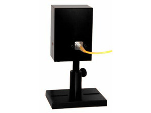
7Z08216This fiber adapter is used to connect a PD300-IRG (InGaAs) sensor directly to a standard FC-type fiber. No mounting bracket is necessary. -
PD300-IRG SMA Fiber Adapter
7Z08222This fiber adapter is used to connect a PD300-IRG (InGaAs) sensor directly to a standard SMA-type fiber. No mounting bracket is necessary.