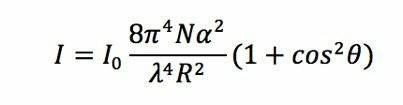
Since the scattered light is viewed from the side the scatter angle θ is 90°. The polarizability, α, is problematic for polarized beams but for typical unpolarized fiber lasers and diode lasers it is not of importance. Of primary concern here for laser measurement is the 1/λ4 dependence, (which is why the sky looks blue) which strongly affects the ability to measure the scatter based on the sensitivity of available cameras.
The scattered intensity is on the order of 10-6 of the beam intensity at λ=1070nm, and standard CCD or CMOS cameras with silicon response have sufficient sensitivity for measurement of kW power beams focused to the several mm and less spot size range. However, for CO2 lasers, the scatter is reduced another factor of 104, and there are no detectors that have sufficient sensitivity to measure even a 100kW beam. Thus from a practical perspective only beams in the 1080 range and below can be profiled using CCD or CMOS cameras. The wavelength range can be increased to the ~1800nm range using InGaAs array cameras, but this is at significant cost increase.
The scattered laser light is imaged from the side using conventional CCD or CMOS cameras with lenses operating telecentrically. The images are captured digitally and processed to obtain the beam profiles. Both CW and Pulsed lasers can be measured. Since the data is acquired at video rates, the measurements are taken in near real-time, making optical adjustments easier and faster to perform.
A profile is obtained for every column of the detector array, so of major significance here is the ability to capture entire sections of the beam caustic. As an example, for common CCD and CMOS cameras with array sizes of say 1090 × 2048, 2048 profiles are captured simultaneously. Each pixel in a column of the image collects the scattered light from a corresponding chord through the beam, so the resulting profiles are equivalent to those obtained using a scanning slit profiler in the direction of the view.
There is a contrasting design requirement that includes both large array size and small pixel size, and lenses that either magnify or de-magnify the beam image. Small pixel size and or lens magnification is needed for small focused beam measurement, in the 50 μm range, and large array size is needed to image focused beam caustics along the path to obtain ~6 Rayleigh ranges for accurate BPP (M2) measurement per the ISO 11146 standard [2].
Thus there are several possible instrument configurations depending on the intended measurement. If only spot size is of importance, then small arrays with small pixel dimension and high magnification can be used. On the other hand, if measurement of M2 and Beam Parameter Product (BPP) is desired, then large arrays and demagnification are required to obtain sufficient Field-of-View.
Instruments can be for single axis measurement, or dual orthogonal axes using two cameras or mirrors to obtain orthogonal profiles using a single camera. It is also possible to obtain multiple views using multiple cameras and mirrors. Also, single axis instrument can be rotated to obtain multiple views at any angle, and tomographic reconstruction can be used to generate more detailed 2D profiles.
ISO 13964 Standard Beam Parameters derived from each profile include [3]:
- Dslit and D4σ Beam Diameters
- Beam Focus "Z" Position
- Beam Centroid Position
- Beam Power
Measurement of the beam caustic allows determination of M2 parameters from the ISO 11146 least squares hyperbolic fit to the caustic diameters. These parameters are:
- M2 Beam Propagation Ratio
- Divergence
- Waist Position
- Rayleigh Range
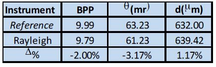
- Beam Parameter Product (BPP)
The relative Beam Power is also calculated for each profile.
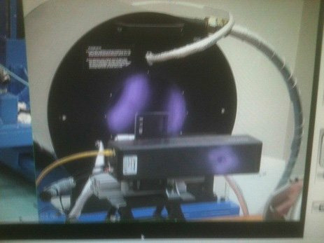
Measurements were performed to evaluate the Rayleigh scatter technique and capabilities using various high-power fiber, diode and disk lasers.
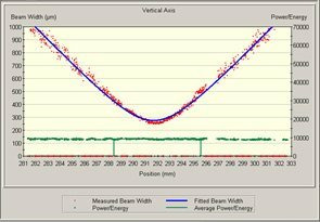
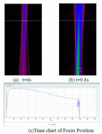
Figure 1 shows a caustic measurement of a disk laser operating at 6kW obtained using a camera with 1392 pixel columns and lens magnification of ~0.4, with equivalent pixel dimension of ~16.125μm. The red points are the raw data for the 1392 profiles, with an observed spread in diameter of approximately10%. The blue curve is the ISO standard curve fit. Since there are so many profiles; 1392 compared to the minimum ISO set of 10, the Law of Averages works in our favor to provide a more accurate beam caustic.

 Ultra-High Velocity