Beam Diagnostics Improve Laser Heat Treatment Effectiveness
Over the years, different approaches have been used to heat treat metals, typically relying on large furnaces where an entire object is subjected to the heating process. This method can consume substantial amounts of energy and is not a useful approach when attempting to heat treat a specific area or portion of the equipment. The use of lasers to perform this heat treating process has become a well-accepted approach. Understanding the beam shape, the uniformity of its intensity, and the cleanliness of the delivery optics all come into play and can significantly affect the efficiency of the approach.
Author:
Dick Rieley, East Coast Regional Sales Manager, Ophir Photonics
A manufacturer of locomotive engine cylinders was applying the heat treating process. In this case, it was important to ensure that the delivered beam met specifications at the beginning of the process. The shape, size, and uniformity of the beam was graphically displayed, quantified, and set up as a baseline using Ophir- Spiricon’s BeamGage® beam profiling software.
One of the key advantages of heat treatment with a laser is localized heating, but delivered in a uniform manner. In heat treatment, this means having a relatively uniform top hat beam is essential to ensure uniform heating and coverage of the target area. Without this imaging and quantitative analysis, the heat treatment process can produce non-uniform results; this can cause the cylinder, once assembled, to be rejected, thus adding costs to the overall manufacturing efforts.
The cylinder manufacturer also needed to know the power density/cm2 values of the laser beam. By calibrating the beam diagnostics to power output through the BeamGage software, the resulting image provided the power density of the beam at points on the beam. The significance of this value was the knowledge that if the power density of the beam was not to the level needed, then the heat of the laser beam will penetrate the cylinder material, a special composite of high-strength steel, to the depth necessary to properly effect the grain structure, resulting in a premature failure in the final cylinder.
In this example, the BeamGage software was calibrated to the measured output power of the laser, which is 6kw’s. The power density/cm2 for the full beam is displayed on the left hand side of the graph. In this image, the beam is delivering at its point of contact on the material 1330 W/cm2, and is quite uniform from side to side, an essential requirement for uniform heating.
Another aspect of laser heat treatment involves attention to the delivery optics of the laser beam. This process can be performed in clean room environments or foundries. In this case, the engine components are being treated in a foundry environment, so the delivery optics of the laser needed to be cleaned on a regular basis to ensure the beam delivered was of the correct size, shape, and intensity.
Dirty optics such as turning mirrors, delivery optics, or laser cover glass affect the beam – typically, expanding the size of the beam and reducing the delivered power to the target point. In either case, the result on the cylinder during heat treatment is undesirable.
Through the use of beam measurement and graphic analysis, we can see the difference between before and after a simple cleaning of the final cover glass over the laser output optics. This cover glass is the most frequently affected surface; ambient dust and debris from the laser process accumulate on the cover glass and need to be cleaned on regular basis. The frequency of cleaning will be determined by comparing the performance of the beam on a periodic basis, such as once a day, and then determining how long between cleaning can be tolerated before deterioration of the beam quality fails specification.
In Figure 1, the beam was profiled with the laser cover glass in place, and had not been cleaned for several days. It is apparent that the top of the beam is not uniform in its intensity, and has a different profile in both the X- and Y-axis. In a process where the optic being treated is moving around, significantly different results will be produced when moving in the X direction vs the Y direction of the heat treatment movement. This is a very undesirable result.
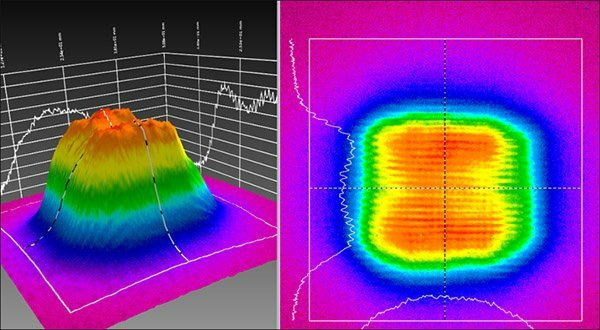
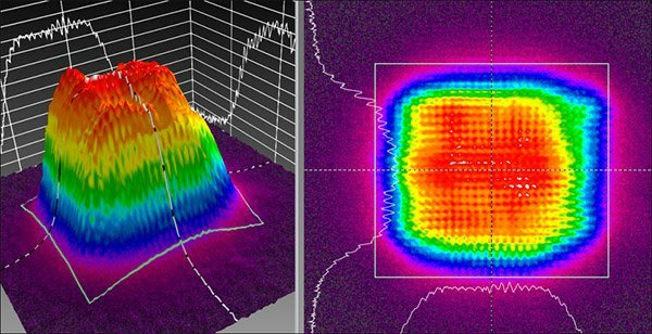
To demonstrate the effect of thorough cleaning of the final cover glass over the laser optics delivery head, the glass was cleaned and reinstalled. The same 6kw of power was delivered. Figure 2 shows the beam size, shape, and intensity, validating that this procedure resulted in a highly desirable effect -- a much more uniform beam pattern.
The next step in this process is to clean any other optics in the beam delivery path to ensure there are no lingering negative effects. The same procedure on these optics can be performed as described above: determine the frequency at which this process needs to be performed to ensure constant and continuous performance of the laser to specification.
Delivering a Uniform, Consistent Beam
Employing laser beam profiling and beam diagnostics software to a laser based heat treating process helped this locomotive engine cylinder manufacturer deliver a beam that was uniform, consistent in its shape, and of the necessary power density to achieve the desired grain structure of the steel composite being processed. Typically, heat treatment of steel composites used in high temperature applications must be heat-treated to reduce the size of the grain structure by a factor of 100. This produces steel that is physically stronger and won’t distort in Kelvin environments. This also eliminates the potential for brittleness that is associated with untreated steel.
The major advantage of using laser beam diagnostics in a heat treating process is cost savings. The common approach to verifying that the heating process has produced the correct gain structure within the metal and has penetrated the material to the proper depth, is through destructive testing using a thorough metallurgical analysis. This process requires removing a statistical sample from the production lot and destroying the product by producing a number of coupons that represent the total treated region. These coupons are then processed through a variety of metallurgical tests that are typically time consuming , costly, and, by their very nature, the results lag the speed of the production line. With laser heat treating, the costly destructive testing process can be reduced in scope or reduced in frequency, delivering significant cost savings to the manufacturer.