Measurement of Mode Field Diameters of Tapered Fibers and Waveguides for Low Loss Components

Many forces drive the miniaturization of optical component technology. Integration of optical components into smaller packages is expected to reduce size constraints, insertion loss, and manufacturing costs. Many ambitious business plans are based on this integrated technology, as it seems amiable to high volume manufacturing methods similar to those found in the semiconductor industry. However, there are numerous technical hurdles to overcome before this Holy Grail is attained.

Major hurdles in this technology are created by the smaller waveguide channel widths. While all sorts of impressive feats can be performed on the waveguide chip, the chip needs to be properly connected to the outside world via fibers to have any value. The most efficient coupling between the waveguide and connecting fibers can be predicted from a parameter called the Mode Field Diameter (MFD). The MFD represents a measure of the transverse extent of the electromagnetic field intensity of the mode in a fiber cross-section. Best coupling occurs between two wave-guides when the MFD of the joined components is identical. Many waveguide channels have an MFD significantly less than standard single-mode fiber. For that reason, tapered, conical, or lensed fibers can be used with these narrow channel waveguides, as these fibers produce beams with smaller MFDs. The MFD is also a function of the wavelength of the light. At wavelengths used in telecommunication applications, 1310 and 1550nm, the MFD of singlemode fiber is 9.2 and 10.5μm, respectively. The loss associated with coupling two waveguides is determined by equation 1:

The MFD mismatch becomes more critical as MFD decreases, which is shown with the following examples. Consider the case of fusion splicing of single mode fiber at 1550nm where the MFD is typically 10.0μm, with a variation of ±0.5μm. Equation 1 indicates the maximum loss due to MFD mismatch is 0.01dB. If the MFD is reduced to 5μm (as often found in erbium doped optical amplifiers) this ±0.5-micron tolerance leads to a greater loss of about 0.05dB. When the MFD is 3μm, a 0.5-micron window leads to a 0.10-0.15dB loss. Larger MFD mismatches than 0.5μm when the MFD is under 5μm can lead to enormous losses of 1 or more dB. Note that these values should be doubled for fiber optic components, as the coupling loss occurs both when the light enters and exits the device.

As the waveguide channels get narrower, it is critical that the MFD of the fibers and waveguides be determined to ensure a low loss component.

Near-Field Measurement of MFD

Attempts have been made to measure the MFD directly at the tip of the fiber. This is known as a near-field technique. With this technique, an imaging microscope objective lens is used, with the focal plane of the lens positioned at the fiber tip. The resultant beam's image is analyzed by a profiling instrument, and the MFD is obtained. While this technique is somewhat popular, it is of questionable value for MFDs under 10μm. This is due to the fact that this technique requires a high level of positioning accuracy and the diffraction limited resolution of the lens becomes comparable to the MFD, as described in further detail below.

The sample positioning requirements of near-field measurements can be found using standard beam propagation equations.

Measurement of an MFD of 3μm to a ±2% accuracy requires a sample-lens positioning accuracy of ~1 micron. This tight tolerance is problematic in research applications. Since expensive positioning equipment, skilled operators, and long testing times are required for accurate near-field measurements, it is largely unworkable from a production point of view.

The diffraction limit of the lens creates even more problems in near-field measurements of small MFDs. The diffraction limited resolution equation of a lens is given by equation 2:,

where λ is the wavelength of the light, and NA is the numerical aperture of the lens. From equation 2, a perfect lens with an NA=1 yields a diffraction limit of 0.95μm at 1550nm, and 0.83μm at 1310nm. Of course, no lens exists with an NA of 1, and most commercially available lenses have an NA no larger than 0.5, doubling these diffraction limit values. Add in astigmatism of the lens, and other optical defects and one understands why the published point spread functions of microscope objectives are typically on the order of 2-3μm, completely unacceptable for accurate measurements of small MFDs.

Far-field Measurements of the MFD

Amore reliable method of determining the MFD of 10μm or less is to measure the source in the farfield. The far-field is defined when the scanning distance z is such that z>>πMFD/λ. As outlined in TIA-EIA Standard 191, once the far-field intensity distribution is obtained, the MFD is generated from the Petermann II integral, equation 3:

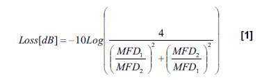
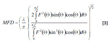
where F2(Θ) is far-field intensity distribution of the test source as a function of the far-field angle Θ for a single dimensional profile1. The Petermann II integral assumes a circularly symmetric waveguide and involves a Hankel transformation of the far-field distribution.

This is a very established method of MFD measurement. Both the National Institute of Standards and Technology (NIST) and its United Kingdom counterpart, the National Physical Laboratory (NPL) use the direct far-field technique to establish MFD standards of optical fiber.

The far-field profile of optical fibers and waveguide sources with an MFD of 10μm or less is quite divergent. For example, for a fiber with a 3 micron MFD, the full width divergence is 40 degrees or larger. Far-field measurements of divergent sources pose a number of unique challenges to be measured accurately in the far-field in order to generate useful MFD results.

In order to measure the far-field distribution of divergent sources, Photon developed a far-field profiling instrument2. This technique was originally developed for laser diodes3,4 and has become the de facto standard for far-field laser diode measurements. It has also proven to be effective and accurate to 0.5% for optical fiber characterization of MFD5. To accommodate the widest range of fibers, Photon designed a far-field profiling system for wave-guides and fibers with more than 60dB of dynamic range of the profile, and a 13.26 cm scanning radius. The large scanning radius minimizes the dependence of the results on sample position, and also reduces bending stress on fibers, which is critical for measurements on polarization maintaining fibers.

This instrument has several distinct advantages over alternative techniques. The first of these is that the light source is measured directly, with no lens, attenuator, or other optics used, which are well known to introduce errors into the measurements.

A second advantage with this tool is that sample positioning has far less influence on the results. Consider the case of a 3-micron MFD. For the near-field measurement, a position accuracy of 1μm was required for an MFD accuracy of ±2%. For a far-field measurement with a 13.26cm scanning radius, ±1% is achieved by a sample position accuracy of ~1mm, more than three orders of magnitude less sensitive. Sample position accuracy of 1mm is easily obtained by simple fixturing, instead of expensive and time consuming positioning equipment.

Results of Far-Field Measurements on Tapered Fibers

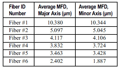
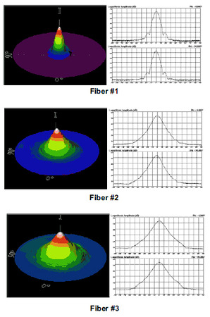
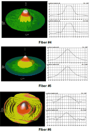
Photon recently conducted a study measuring commercially available tapered and lensed fibers to better understand the issues surrounding MFD measurements of these fibers. The results were generated using a Photon Model LD 8900HDR Far-Field Profiler with the fibers coupled to a stable, narrow-linewidth source operating at a nominal wavelength of 1550nm at an output power of 7 dBm. The full 3-D far-field profile and two orthogonal 1-D cross-sections are displayed below, as well as the average Mode Field Diameters determined from the Petermann II integral.

What emerged from the data was that the tapered fibers produced highly non-Gaussian beams. For standard single mode fiber, it is well known that the light is not Gaussian but is actually best approximated by a Bessel function. However, to a reasonable first-approximation, a Gaussian function is often used in modeling light from single mode fibers. The tapered fibers in this data set deviated much more significantly from a Gaussian, casting additional doubt on the validity of a Gaussian approximation with these fibers.

In the case of Fiber #6, we were able to accurately obtain the far-field profile, divergence angle and numerical aperture of this sample over the major and minor axis. However, as this fiber produced an elliptical beam, the validity of the Petermann II integral for MFD calculation on this sample is questionable. However, some MFD analysis can be performed on samples on non-circular geometry where the Petermann II integral may not apply.

Determining MFD for Arbitrary Sample Geometries

In these situations, the divergence angle from the far-field measurement may be used to determine the MFD, without resorting to the Petermann II integral. From the far-field divergence angle of a purely Gaussian beam, the MFD is determined by:

from diffraction limit considerations. The full divergence angle Θ is in units of radians and λ is the wavelength of light. Therefore, one simply determines the divergence angle of the source and extracts the MFD from this angle, assuming the profile is Gaussian. This technique has the advantage that it makes no assumptions about the geometry of the source. For that reason, it can be applied to waveguides and elliptical fibers, which are not circularly symmetric, while the Petermann II integral may not appropriate. We have observed reasonable accuracy (±5%) of MFD values determined this way for single-mode fibers and other sources with near-Gaussian beams. (In a few cases, fairly "ugly" beams still produced reasonable results.) Of course, if the source produces a significantly non-Gaussian beam, equation 4 will not apply, although it will determine the lower limit for the MFD. A waveguide producing a highly non-Gaussian profile is usually not desirable. Therefore, the far-field profile may be sufficient to determine whether the source is suitable for use in production, and determine the MFD if the profile is sufficiently Gaussian.

The Path to Optical Integration

As engineers and scientists push to provide more optical functionality in a smaller area, and create devices that can be fabricated cheaply and in high volume, coupling these devices to external fibers efficiently is still important. An unfortunate byproduct of this miniaturization is that coupling these devices to single mode fibers is more challenging, and more prone to render the device useless, if the MFD of the components are not comparable. Mode field diameter measurements from the far-field distribution pattern provide a means to qualify components quickly in these applications so that the full benefits of this technology can be realized.

References

  1. "Measurement of Mode-Field Diameter of Single- Mode Optical Fiber", Fiberoptic Test Procedure FOTP-191, Telecommunications Industry Association, Standards and Technology Department, 2500 Wilson Blvd., Suite 300, Arlington, VA, 22201 (1998)
  2. U.S. Patent Number 5,949,534, "Goniometric Scanning Radiometer", Granted September 7, 1999
  3. 3 Derrick Peterman and Jeff Guttman, "New Approach Improves Far-Field Measurements", Laser Focus World, July 2001
  4. 4 J.L. Guttman, J.M. Fleischer, and A.M. Cary, "Realtime Scanning Goniometric Radiometer for Rapid Characterization of Laser Diodes and VCSELs", Proceeding of the 6th International Workshop on Laser Beam and Optics Characterization, Munich, Germany, June 18-20, 2001
  5. 5 J.L. Guttman, R. Chirita, and C.D. Palsan, "A Novel Far-Field Scanning Technique for Rapid Measurement of Optical Fiber Parameters", Technical Digest Symposium on Optical Fiber Measurements, 2000, National Institute of Standards and Technology, Boulder, CO, September 26-28, 2000.
Contact Us illustration

Have questions? Require assistance?

Click below to to contact Ophir Photonics and we'll get back with you shortly.

Contact Ophir Photonics