Energy Sensors: Response Time, Integration Time

There seems to be a good deal of confusion when it comes to the terms “response time” and “integration time” of energy sensors. In this article we will clarify the meaning of these terms, as they apply to Ophir’s pyroelectric “Smart Sensors.”

Author:

Mark Slutzki , Product Manager, Ophir Photonics

Confusion time…?

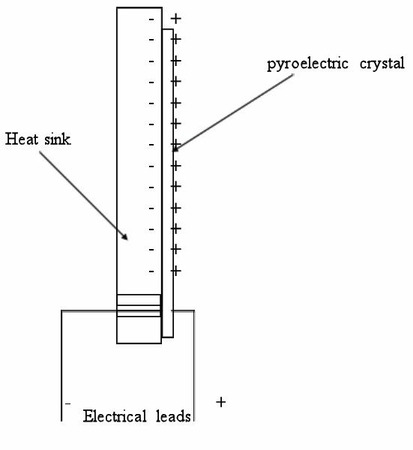
Pyroelectric sensors use a pyroelectric crystal. When a laser pulse is absorbed, it is turned into a heat pulse in the crystal, and the crystal then generates an electric charge proportional to the heat absorbed. Since the two surfaces of the crystal are metal coated, the coated crystal in effect becomes a capacitor; the total charge generated is collected (and therefore the response is not dependent on beam size or position) and becomes a voltage pulse, which gets measured.

It looks schematically as follows:

The response time of the pyroelectric sensor (not to be confused with integration time – we’ll get to that shortly) depends on the time it takes for the heat to enter the crystal and heat it up. For metallic type pyro detectors, this time is on the order of µs and thus the metallic type can run at a high repetition rate. For the BF and BB black coated types, the response time is on the order of ms, with a correspondingly lower repetition rate.

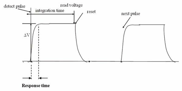
The integration time is something else – it is the time during which we hold the voltage signal as it maximizes and stabilizes so we can measure it. At the end of the integration time, we “reset” the voltage back down to zero so the sensor is ready for the next pulse. The time it takes for this reset depends on the thermal relaxation time of the sensor and on the RC time constant of the electronics.

In other words, the integration time is the “time window” during which a given pulse is measured. This explains, it should be noted, why choosing a given “Maximum pulse width” setting determines the maximum pulse repetition rate, as can be seen in the specifications.

It looks as follows:

When the user sets the “maximum pulse width,” for example 2μs, this sets the integration time. Even if the pulse width is actually only 3ns, the sensor will hold the voltage for 2μs (in this example) and “integrate it,” i.e. collect and measure it.

If the pulse is actually longer than 2us, yet one sets the “maximum pulse width” to the 2us setting, some of the pulse will be cut off and ignored (resulting of course in an incorrect reading). If, on the other hand, the “maximum pulse width” setting is set to much longer than the actual pulse width, that allows some extra noise to get in; in general one should choose the shortest “maximum pulse width” setting that is still definitely longer than the pulse.

Contact Us illustration

Have questions? Require assistance?

Click below to to contact Ophir Photonics and we'll get back with you shortly.

Contact Ophir Photonics