High Power, Cramped Spaces - Measurement Challenges in Additive Manufacturing

Laser-based additive manufacturing is transforming industrial processes and opening up new horizons in a variety of application areas. In the aerospace and automotive industries, for example, it makes it efficient to manufacture intricate parts according to lightweight construction principles; in medical technology, it has expanded the range of prostheses and orthoses; and in toolmaking, it shortens the time it takes to implement new requirements. Long since AM applications have attained a level of maturity that allows for series production – but when it comes to checking the laser beams in the construction chamber, process experts are often presented with major challenges. Fortunately, new developments in the field of measurement technology now enable the rapid measurement, directly in the construction chamber, of the kind of high-power laser beams used in selective laser melting (LPBF, or 'laser powder bed fusion').

Author:

Nicolas Meunier and Luca Porcelluzzi

Laser protection with consequences

LPBF systems melt thin layers of metal powder through selective heat input using a fine laser beam. Since metals have a higher melting point than plastics, for example, it takes powerful lasers to melt the powder layers. For this reason, the melting process must take place within a protected construction chamber, as it is the only way to comply with the safety requirements. At first glance, this seems both straightforward and logical, but it presents other challenges in terms of adhering to the process parameters. Because LPBF systems are based on state-of-the-art laser technology and usually operate at high power densities, traditional measurement technology for lasers is only of limited use here: either the devices cannot measure all the parameters, they do not fit into the production chamber, or it would take too much time to set them up correctly. This is especially true when, to ensure the comparability of the measurement results, a continuous measuring method is foreseen for all process stages.

Figure 1. Measurements of the laser beam parameters are essential at various stages of the development and production process in additive manufacturing.

Different measurement methods

LPBF systems are available from numerous manufacturers, and for larger build jobs, multiple laser systems work together within a build chamber on a single part. Even though – in contrast with other tools – the laser source itself does not wear out, there is often a degradation in quality that occurs as the beam travels from the source to the building plane (see Figure 2).

Figure 2. The beam profile can change significantly on the way from the source (left) through delivery (canter), and to the laser processing head (right).

If such changes go undetected, the production quality suffers without being noticed. Particularly in critical components for medical technology, but also with safety-relevant parts for the aerospace industry, even the tiniest differences can put the stability of the entire system at risk. Therefore, close examination of the laser beam should be integral to each and every stage of the manufacturing process. But which parameters should be measured, and which measurement methods are practicable for this purpose?

These are the parameters used to evaluate a laser beam:

  • Power and energy
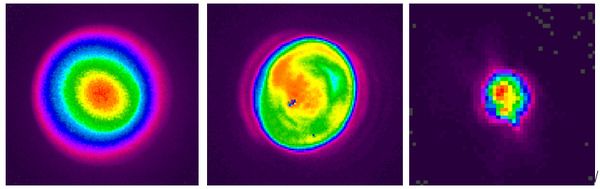
  • Spatial intensity distribution
  • Focus position
  • Beam quality
  • Divergence
  • And: the stability of these parameters over time

Power and energy measurement

Often, in order to detect changes in the laser beam, one measures its power or energy. The measurement technology for this is long established, and – depending on the laser type, power level or energy – there is a wide range of thermal, pyroelectric and photodiode sensors available. However, when it comes to LPBF applications, there are several limiting factors to consider:

  • The power or energy density in LPBF applications is often so high that thermal sensors would require additional cooling
  • Since the build chamber is always very dusty from the metal powder, the delicate sensor surfaces must be shielded from it
  • The build chamber is cramped, so there is no room for any extensive measuring setup
  • To operate the laser, the door to the build chamber must be closed frequently, which makes cables problematic

These limitations, along with the ever-growing number of applications for AM technology, are driving the manufacturers of measuring instruments to develop individual metrological solutions for LPBF systems. MKS Instruments has now introduced a new, ultra-compact power gauge that was specially developed for measuring high powers in confined spaces. The footprint of the Ophir Ariel measuring device is about the same size as a standard playing card and fits comfortably on the palm of your hand. The battery-operated device shows the measurements directly on its display, saving them internally or sending them via Bluetooth to a receiving device outside the build chamber. Not only does it meet the dust protection requirements, the system is self-contained and splash-proof. In order to cover a wide measuring range from 200mW to 8kW without requiring additional air or water cooling, the Ariel power gauge combines two operating modes: (a) brief measurements of the energy for high-power lasers up to 8kW, and (b) continuous power measurements for lower powers up to 500W. Due to the system's high thermal capacity, several consecutive pulses with an accumulated energy of 14kJ can be measured before it has to cool down. For laser beams with high power but a smaller diameter, the removable diffuser (included) enables safe power measurement.

Figure 3. The Ophir Ariel power gauge can be used even in small build chambers (picture taken at Leibniz Institute for Solid State and Materials Research Dresden)

Compact power gauges designed specifically for additive manufacturing deliver major benefits to both manufacturers and operators of LPBF equipment. The fast power measurements can be integrated into any process, thus reducing the obstacles to process monitoring. The more frequent the measurements, the faster it is to detect trends that indicate a change in the laser beam. Just as the wear and soiling of optics and protective windows over time is a gradual thing, so are the slow changes in laser power occurring on the building plane. The solution is not to simply increase the laser power, but rather to go looking for the source of the problem as soon as the process window can no longer be met. The service technicians of laser system manufacturers also stand to benefit from such compact power gauges: there is less weight to carry around, setting up the measurement goes quickly, and the results are available in three seconds. If the measured power deviates from the expected power, then more detailed investigations are called for. Once the classic sources of error have been ruled out, a close examination of the laser beam itself is often the next step.

Beam caustics and focus shift

A wide range of beam parameters is provided through non-contact measurement of the laser beam based on the phenomenon of Rayleigh scattering. Also with this technique, its great virtue is that it requires no additional air or water cooling, so it too can be used in LPBF systems. The measuring technology was developed by MKS and further enhanced in the Ophir BeamWatch AM measuring instrument, which was designed specifically for use in additive manufacturing. Non-contact measurement proves of particular benefit with high power densities, such as those frequently used in additive manufacturing. Since the device can record up to 1 kW of power over a span of more than two minutes without needing active cooling, it can be used in research and development as well as in production and service. For example, if an LPBF process is continuously monitored via power measurement and the power falls at the building plane, then the beam profile measurement provides laser beam parameters that can be instrumental in pinpointing the cause of the drop in power. Beam position, angle of incidence, focus size and position – as well as quality parameters such as M² and beam caustics – can all be determined in real time. These measurements immediately provide the user with information as to whether the beam is aligned and in focus at the building plane. Comparability of the measurement results, which plays such a crucial role for system manufacturers, is guaranteed at all times.

Figure 4. The Fraunhofer facility for additive manufacturing technologies (IAPT) during beam analysis at an LPBF plant. (©IAPT)

For detailed process analysis in LPBF plants, non-contact measurement provides another decisive advantage: it determines focus shift, that is, any change in the focus position. The focus position of a laser beam is influenced by thermal effects on laser components and beam guide, in particular on transparent optics such as lenses or protective windows. If this moves despite constant distance between the focusing optics and the material, there will be a change in the power density – and thus also in the behavior of the material being worked by the laser beam. In order to avoid losses in quality, it is imperative to know the focus position in relation to the material to be processed. Classic measuring devices generally measure too slowly to be able to detect any drift in the focus position. While they seem to indicate that the processes are stable, in truth they just cannot measure focus shift at all. Non-contact measurement, on the other hand, takes only fractions of a second and provides a realistic picture of the process.

Conclusion

Measuring the laser beam in LPBF processes contributes decisively to ensuring product quality while optimizing the process in terms of sustainability. New metrological possibilities reduce to a minimum the time required for taking measurements during processing, and the investment made in the equipment pays for itself very quickly. For the first time, unexplained errors and phenomena in additive manufacturing can be measured and explained. This represents concrete steps taken towards increasing reproducibility and achieving series production.

Contact Us illustration

Have questions? Require assistance?

Click below to to contact Ophir Photonics and we'll get back with you shortly.

Contact Ophir Photonics