VCSEL Near-Field Profiling and Testing in Production

VCSELs are used in diverse commercial, industrial and consumer device applications. The latest developments of the technology have paved the way to state-of-the-art 3D sensing applications. Combining different testing techniques for optical quality control and characterization – such as VCSEL optical power and energy output measurement, as well as far- and near-field beam analysis – proves to be the most effective way to assure the quality of the VCSELs while efficiently attaining the strived-for production yield. While far-field testing, e.g. with the Ophir Wide Beam Imager (WB-I) as well as power measurement with integrating spheres are designated to analyze entire VCSEL arrays, near-field analyzers allow testing both entire arrays and individual emitters of a VCSEL die.

Challenges in near-field analysis

Near-field analysis is gaining more and more scrutiny for potential use in automated test systems for high-end VCSEL production lines. In order to create the finest laser source components that comply with the elevated quality standards, it is imperative to check each emitter individually. This technique locates the positions of all single emitters and measures their homogeneity and intensity.

To achieve best measurement results in near-field analysis, the following key conditions must be met:

  • The measurement device should deliver high image resolution as a prerequisite for detecting any issues on the VCSEL array.
  • It needs to cope with large divergences, as this is common with VCSEL beams.
  • A wide field of view (FOV) enables the measurement of large VCSEL arrays.
  • As space constraints are usually a given in automated testing benches, the compact design of the measurement tools becomes important.

Near Field Analyzer – wide FOV, 90°

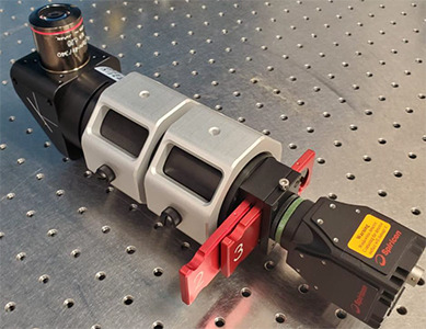
Each VCSEL array is assembled from numerous individual emitters. Ophir's new Near Field Analyzer – wide FOV, 90° enables beam profiling and validation of relevant parameters at the individual emitter level by combining the Ophir BeamGage software with a beam profiling camera and a specially designed microscope objective.

The instrument makes it possible to create images of the beam profile with resolution as high as 1μm or 10% of the size of the individual emitter. Its combination of a large divergence (acceptance) angle of up to 35°, its wide FOV of 2.3 x 2.8 mm, and a wide range of allowed power outputs makes it an ideal tool for both R&D and production-line testing purposes.

Its 90° compact design facilitates integration into various automated testing benches and setups.

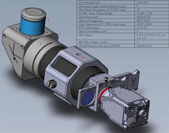
Scheme and Specifications

  1. Microscope objective (x4) with a large numerical aperture (NA) and pupil size that enables the observation of beams with divergence up to 35 deg, and with a large FOV while providing a high-resolution image.
  2. 90° prism mount is used for beam splitting and power attenuation. The beam splitting permits simultaneous measurement of both the VCSEL array's near field and, with a power meter or an integrating sphere, its emission power. In addition to beam attenuation, the 90° design allows the Near Field Analyzer device to be used in constrained spaces, such as testing benches or small chambers.
  3. Infinity-corrected tube lens assembly
  4. Mount with M6 threads
  5. Filter mount, permitting adjustment of the optical output for optimized beam profiling via manually interchangeable ND filters in UV/ VIS or NIR regions of the following ND values: 0.3, 0.7, 1.0, 2.0, 3.0, 4.0. This allows measurement of a wide range of VCSEL powers from just a few μw up to 1 watt.
  6. LT665, 1" CCD format beam profiler with BeamGage software, offering a high frame rate of 27 frames per second (FPS), a highly dynamic range, and the ability to remove stray light through its Ultracal feature.

The overall compact dimensions, requiring just 135 mm of space between the bottom of the Ophir Near Field Analyzer and the measured VCSEL, means the instrument fits into a narrow chamber, such as are found in automated test systems.

Measurements

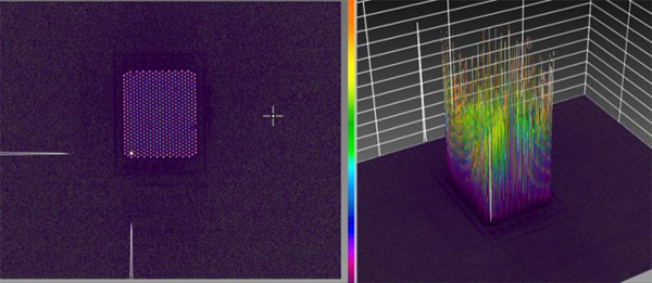
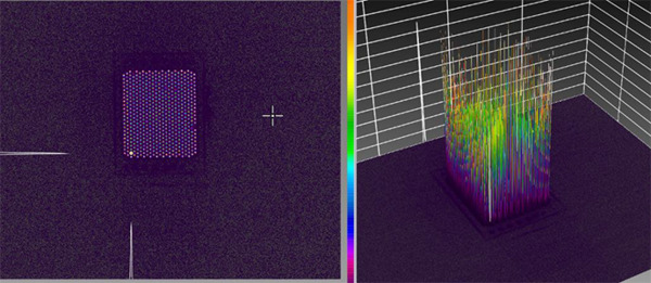
Wide FOV enables to measure large arrays up to 2.3 x 2.8mm:

BeamGage image of VCSEL profile, 2D and 3D measurements. The Near Field Analyzer lets BeamGage users test individual emitters as well as entire arrays to identify and quantify any malfunctioning emitters.

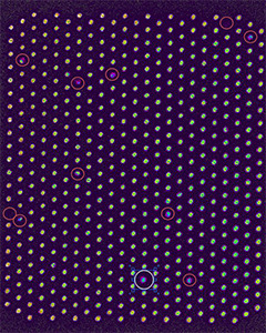
Enlarging the image of the VCSEL array permits quantitative analysis of each individual emitter and locates the malfunctioning ones (marked with red circles).

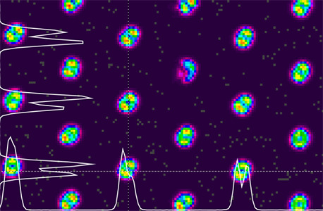
Further enlarging the VCSEL image reveals the visual deviation of the emitters' profiles and their quality.

Light-current-voltage (LIV) sweep test

Emitter behavior during the LIV sweep test is an important factor in every laser diode-based system.

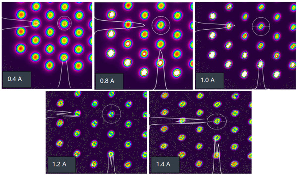
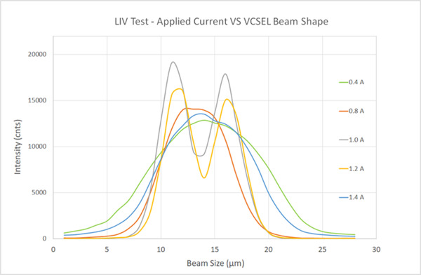
VCSELs are in highly divergent emission mode, called "LED mode", when there is only a low drive current applied. When the drive current of a VCSEL is increased, however, its beam profile quickly changes to a directed-emission "laser mode". This shift happens very rapidly; detecting the exact electro-optical values during this process is critical.

The Ophir Near Field analyzer enables accurate observation of every single emitter in the VCSEL array during the LIV sweep test:

BeamGage images and beam profiles of the emitters during the LIV sweep test – characterization of individual emitter intensity vs. applied current (normalized), at 0.4, 0.8, 1, 1.2 and 1.4 A.

Conclusions

  • Near Field Analyzer – wide FOV, 90° makes it possible to measure both individual emitters and entire VCSEL arrays. The combination of high image quality, high resolution, high divergence tolerance, and large FOV as outlined above is essential for this process.
  • Used together with the powerful BeamGage software, the system performs accurate quantitative testing of VCSELs, whether during the production process or in final product testing.
  • With its compact, 90° design, the device can easily be fit into constrained spaces.
  • The large selection of adjustable ND filters and large dynamic range makes it possible to measure a wide range of power densities in both pulsed and CW operation modes.
Contact Us illustration

Have questions? Require assistance?

Click below to to contact Ophir Photonics and we'll get back with you shortly.

Contact Ophir Photonics