Laser Power as an Indicator of Process Quality

Is additive manufacturing ready for mass-production? The answer really boils down to reproducibility. When it comes to selective laser melting, both the manufacturers of the laser systems and the users thereof have recognized that the constancy of the laser parameters is of great importance in the production process. But is it possible to test this quickly and cost-effectively during operation? Learn how measuring the laser power is a good indicator of changes – and what pitfalls can arise.

Five crucial questions to ask when developing a measurement strategy

In order to reliably and stably build up the individual layers of an additively manufactured component, besides a suitable base material it requires a laser beam that is optimally adjusted to the process – or in larger systems, several of them. Especially with regard to reproducibility, it is crucial to check that the laser beam always meets the specified parameters whenever it hits the working plane. As these systems are being developed and produced, the laser beam’s exact parameters are initially set and verified. While more complex beam profile measuring instruments are usually employed in this case, some of these measuring tasks can be performed perfectly well with power gauges. For additive manufacturing purposes, continuous monitoring of the laser beam is necessary even while the system is running. Cost-effective and fast, power gauges can provide important information about the changes taking place within the process. First, however, it is necessary to define a requirements profile for the measurements and to rule out possible error sources.

What is the goal/purpose of measuring?

This question is the starting point for all further considerations. In principle, it is important to decide whether you want to determine absolute values or carry out comparative measurements. Comparative measurements are good for detecting anomalies and power losses that may occur, for example, in a maladjusted system. In general, when conducting comparative measurements, it is recommended to always use the same measuring instrument – or, if several instruments must be used, the same sensor type – in order to increase the repeatability of the measurements. If absolute values are what is required, care should be taken to ensure that the absolute accuracy of the selected instrument is very high.

Where will the measurement be carried out?

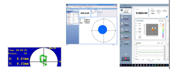
Perhaps the most direct measuring method is to take the laser power at the building plane. However, in order to prevent damaging the sensor, care must be exercised to ensure that the power density of the destruction threshold is adapted to the sensor coating. This can be achieved by measuring the laser beam not at the focal point but rather with the working surface lowered. If the power is measured at different points in the build space, it can be determined whether the beam is vignetted or not. If this is the case, the adjustment of the laser system must be checked. Power measurement in the build space can be conducted by end users, manufacturers and service technicians. The quadrant sensors (PPS), which measure not only the power but also the position and size of the beam, go a step further than conventional power gauges. They are used inside the construction chamber. When the sensor is positioned centrally and moved vertically, the beam position should not show differences. Any change in the measured beam position indicates an offset in the deflection head or a misalignment in the beam path. To a certain extent, this sensor technology can also be used to determine the accuracy of the beam adjustment in the peripheral areas of the building plane – in terms of both power and beam position.

Figure 1. Measurements taken with PPS sensors can provide first indications of the status of a laser-based system.

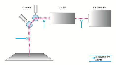
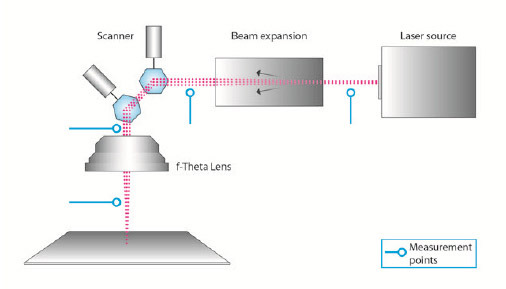
A power gauge can also be used to measure the components in the laser beam path. A distinction is made between two different systems: 2-axis mirror galvanometer (galvo) systems with an F-theta lens or 3-axis galvos (see Figures 2 and 3). To determine possible losses at the individual elements, power measurements can be carried out between the individual components. While measurements in the beam path of the laser are mainly of interest for the manufacturer of the laser system during the design and manufacturing process, they are also useful for troubleshooting or maintaining a system.

Figure 2. Structure of a 2-axis galvo system: Measurements between the components provide information about their function.
Figure 3. Construction of a 3-axis galvo system: Here, too, measurements can be taken between the components.

How to select the right sensors?

In principle, the power of the laser beam to be measured should be in the upper dynamic range of the measuring device without oversizing the sensor. If they are to be used to measure in only one laser system, for thermal power sensors it is recommended to choose the smallest possible diameter: The heat is conducted more quickly to the outside and/or the back, where it is converted into electrical signals. The measurement then goes much faster or has a higher temporal resolution than with a larger area. Here, due to the greater sensor mass, conduction of the heat takes longer, and so does the measurement. Furthermore, when selecting a sensor, the damage threshold of the sensor’s coating must be taken into account. When calculating the power densities, it is important to know the respective beam profile. A Gaussian beam has significantly higher power densities in the center than would be the case with a perfect tophat profile. In addition, some laser sources are likely to have spikes that can also damage the sensor. Ophir's measurement experts recommend using the calculators that are available on the company's website. The power densities of a Gaussian beam can also be calculated there.

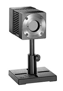
Figure 4. Example of a 4-quadrant sensor, the Ophir F150A-BB-26-PPS

What are the additional sources of error?

For measurements taken on the building plane, the measurement arrangement poses a great challenge: If the sensor is placed at the edge of the plane, then one must take into account the angular dependence of the absorption of the sensor’s coating. This information is provided by the manufacturer of the measuring device. If the angle is too large, it produces a measuring error that must be corrected. Another peculiarity that can lead to measurement errors is if the beam diameters are too small. Since the coating of the sensor disk has a certain roughness, the beam diameter should ideally have a minimum size of 3-4 mm to ensure measurement accuracy. Furthermore, the beam should not hit the edges, but stay as close to the center of the sensor as possible. On the other hand, the beam diameter must not completely fill the aperture, otherwise measurement inaccuracies may occur. 60–70% is a guide value here, which leaves enough room for adjusting the sensor and avoids over-radiation or clipping.

How to optimize the measurements?

While the repeatability of technically high-quality sensors is usually in the range of a few tenths of a percent, depending on the sensor technology, the absolute accuracy is usually in the range of +/-3–5% and thus covers all power ranges and wavelengths of the sensor. If, however, a measurement is carried out primarily at one given measuring point in terms of power and wavelength, this operating point can be considered in a special calibration. This way, the absolute accuracy of the measurement can be improved by about 1%, for example from 3% to 2%.

Overall, one should keep in mind that continuous operation causes undue stress on power gauges. In order to prevent functional damage, it is recommended to carry out regular visual inspections. Strong discolorations or shiny spots on the absorber surface, for example, are the first warning signs of local overloading of the coating. Moreover, the sensor should be calibrated regularly to ensure high repeatability and absolute accuracy in the long term.

If one is observing changes in a high-power laser, comparative measurements can be carried out at lower powers. The decisive factor is to always select the same settings, so the results can be compared against one another.

In summary

One thing is certain: Not measuring is no alternative for laser systems in additive manufacturing. Another undisputed fact is that the instruments for measuring beam profiles that also have integrated power measurement provide the most comprehensive results. In some cases, though, this measurement technology is simply out of reach for economic reasons. However, with the clever choice of power gauge – or PPS sensors – combined with the appropriate measuring strategy, the user can obtain a comprehensive diagnosis of the equipment’s condition. The advantages are obvious: They safeguard the investments that have already been made, prevent quality problems, and they produce sustainably since the machine hours, material and energy are all used optimally.
Contact Us illustration

Have questions? Require assistance?

Click below to to contact Ophir Photonics and we'll get back with you shortly.

Contact Ophir Photonics