White Paper – ISO compliance of non-contact, real-time beam analysis

During the past decade laser power levels used in production applications has risen significantly. Today, welding systems are commonly using laser power in the range of multiple kilowatts. To deliver continuously high product quality, the key parameters of the laser beam must be measured on a regular basis. Ophir has tackled the task and developed a non-contact measurement technology based on the Rayleigh scattering. The technology used in the BeamWatch laser beam profilers enables the measurement of high-power beams without ever touching the laser beam. As the technology is relatively new, it has not made its way into the ISO standard. Nevertheless, it is of high relevance for the users of fiber laser technology to trust on the accuracy and repeatability of their measurements. Here we show that non-contact beam profiling based on Rayleigh scattering fully complies with the ISO11146 standard.

Author:

Jed Simmons Ph.D. & Kevin Kirkham

In this white paper we will produce and disseminate an explicit comparison between Rayleigh Scatter based beam profiling methods and other beam profiling techniques used to measure beam propagation parameters. The goal is to determine whether these technologies provide similar results and if these results comply with the ISO guidelines for measuring laser beam widths, divergence angles and beam propagation ratios.

Herein it is shown that multiple systems based on various measurement technologies produce similar results and thus provide confidence in the accuracy and usefulness of the technologies involved. This document also addresses why it is thought Rayleigh scatter observations of laser beams are especially useful when more traditional laser beam measurement techniques are inconvenient or are not possible.

What follows is a summary of the different systems and their measurement results. Three parameters are reported, the waist widths W0x and W0y, the divergence x and y, and the M-squared, Mx2 and My2 for both axes. Rayleigh length, Zᵣ is also included. An effort was made to ensure the axes of the BeamWatch, NanoScan, and BeamGage SP920 was oriented coincidentally. The research focuses on the Gaussian beam profile as this is widely used in high power material processing.

Laser

An alta Prime 1kW single mode fiber laser from nLight, Vancouver, WA was used for all testing referenced in this paper. A vertical delivery head with a 30 mm focal length collimating lens and a 125 mm focal length focusing lens was used to create the focal region or caustic of this 1080 nm fiber laser. The laser was operated in CW mode and was never modulated in the course of these measurements.

Laser Specifications from the manufacturer ¹ – Note the single mode fiber option was used.

Measurement System

The beam was measured with four different Ophir systems.

  • NanoScan 2s Ge/9/5 model NanoScan™ scanning slit technology-based beam profiler.
  • High Resolution SP920 model silicon CCD camera using BeamGage Professional laser beam profiling application.
  • BeamWatch Non-Contact Beam Profiler model BW-NIR-2-155 using Rayleigh scattering.
  • BeamWatch AM model BW-NIR-2-50-AM integrated laser beam profiler / power sensor system using Rayleigh scattering.

All systems either measure the focused laser beam caustic at once and without translation along the propagation axis or were translated along the optical axis of the laser beam so as to capture data at the same or nearly the same points.

NanoScan™ Scanning Slit Sensor

The mechanical configuration of the main components of the scanning sensor include the scan drum with optical position encoder and motor, scan slits, a stationary large area single element detector. NanoScans⁵ employ Silicon, Germanium and Pyroelectric detectors. The NanoScan used for these measurements used a Pyroelectric detector. The scanning slits were 9mm long and 5um in width.

Scanning slit based beam profilers employ microscopic slits mounted orthogonally such that part of the impinged laser beam transits the slit and is detected by a single element sensor. As the drum rotates, a high-resolution optical encoder mounted on the drum describes the location of the slits⁵. The signal from the detector represents the integrated profile of the beam under test in the axis orthogonal to the direction of the slit. By subsequently digitizing the signal produced by a beam as it transits both slits, the intensity distribution as integrated along the scanning axis in both X and Y axes of the beam can be measured. Considering the beam propagation axis, the plane of the slits becomes the measurement plane. The rotation speed of the drum and frequency of the sampling of the digitization of the single element detector as a subset of the rotation transit time becomes the spatial resolution of the measurement system. In the case of the NanoScan model NS2-Pyro-9/5 this sampling frequency represents an effective "pixel" size of 125.2nm.

Scanning slit beam profilers benefit from the very large dynamic range of a single element detector and the large attenuation provided by shining a beam through a microscopic slit. In many cases additional optical attenuation is not required to maintain the optical signal intensity below that of the saturation of the detector.

SP920 CCD Camera with BeamGage

The laser beam under test directly impinges on the camera-based laser beam profiling system's CCD or CMOS sensor. Significant optical sampling and attenuation are required to keep the optical signal within the linear range of the matrix sensor. The camera that was employed uses the Sony ICX274 sensor, Resolution: 1624 x 1224, Pixel pitch: 4.4um. Pixel spacing and thus the optical resolution of the system is based on the micro-lithography techniques used to create the sensor. These techniques are similar to those used to fabricate other silicon based integrated circuits such as memory chips and micro-processors. Laser beam width measurements based on this technology have an accuracy of 1 to 3%. Variables affecting accuracy include; the how close to the saturation level of the camera the impinged beam intensity is, number of pixels covered by the laser beam, measurement algorithms that are employed, and software apertures used to reduce the data set. The BeamGage² beam profiling software suite employs a sophisticated baseline balancing feature called UltraCal. By effectively nulling the camera baseline, beam width maximum measurement accuracy is realized. Balancing the noise about zero is essential because the beam measurement computations do not distinguish between camera/measurement noise and optical signal.

BeamWatch Rayleigh scatter-based system

The Ophir BeamWatch³ system utilizes the atmospheric scatter to image the laser beam caustic from the side or orthogonal to its axis of propagation.

The native resolutions of these measurements are defined by the 5.5 μm pixel size of the camera used to view the beam and the magnification of the imaging optics. The beam is viewed in X and Y axial views. Each row of the camera image becomes an equivalent to a moving slit beam width measurement. From these beam widths X and Y hyperbolic fits are created.

These fits yield the waist location, divergence and Rayleigh length measurements of each axis. From the entire measurement space three Rayleigh lengths on either side of the waist can be measured.

BeamWatch software provides the raw beam images with false color pallet applied. The application also provides a 2D image of the cross-section intensity as located by a moveable cursor. The software also provides a depiction of the calculated fit, and 3D image of the beam caustic in a stack of coins type display.

BeamWatch AM integrated Rayleigh scatter-based system

The BeamWatch AM is identical to the standard BeamWatch but with the addition of a thermopile type 1kW power sensor. This power sensor is calibrated to a National Institute of Standards and Technology (NIST) traceable detector and comes with a calibration certificate that includes the traceability chain to NIST calibrated power sensors used in the substitution style calibration of the integrated sensor. This fan cooled sensor also acts as a beam dump as it safely captures the beam as it exits the area of the Rayleigh scatter measurement path.

With the addition of the power sensor, the BeamWatch is knowledgeable of the total power in the beam under test. This allows the system to report all portions of the caustic with power over area (power density) values such as Watts per square centimeter (W/cm²).

Now, the measurement instrument can document the power density that is available to do the work of melting the metal powder used in the additive processes.

Calibration Criteria

Camera CCD Sensor, the sensor manufacturer's pixel pitch is used in all spatial measurements. Industry standard microlithography fabrication tolerances are assumed. Beam width measurement systems are compared using Statistical Process Control (SPC) methods. Limiting factors include; beam width measurement technique, limiting aperture, and number of pixels covered.

Scanning Slit, the drum scan rate & spatial sampling interval measurements was calibrated with industry standard devices. The slit was measured with Scanning Electron Microscope. Limiting factors include, slit width, drum speed stability, and amplitude of optical signal. Minimum optical signal must exceed 20 times the noise of the sensor system. In all cases mentioned here, the optical signals provided to the NanoScan exceeded 100s of time the noise of the NanoScan system. Rayleigh Scatter, imaging system magnification is confirmed with NIST traceable reticle. Beam width measurements compared using SPC methods Limiting factors include, signal to noise ratio, number of Rayleigh lengths captured in measurement.

Data Acquisition Set-up

The data acquisition system for the CCD camera and scanning slit NanoScan system was mounted on a translation stage so that the sensor could be moved along the optical propagation axis with good accuracy and repeatability.

The BeamWatch data was acquired with the systems measurement area placed about the waist of the laser under test. A water-cooled thermopile type laser power sensor was used to measure laser power and to serve as a beam dump.

Ten measurements were made with each system. These measurements were averaged, and the average measurement was compared to the average of the measurements from all four measurement systems.

The measurements and the variation of each measurement average was compared to the average of all four systems

Measurement Data - NanoScan based on scanning slit technology

Measurement Data - SP920 CCD camera with BeamGage using CCD technology

Measurement Data - BeamWatch using Rayleigh scattering

Measurement Data - BeamWatch AM using Rayleigh scattering and Laser Beam Power Sensor

Data Comparison

Correlation to ISO Standard 11146-1: Stigmatic and simple astigmatic beams

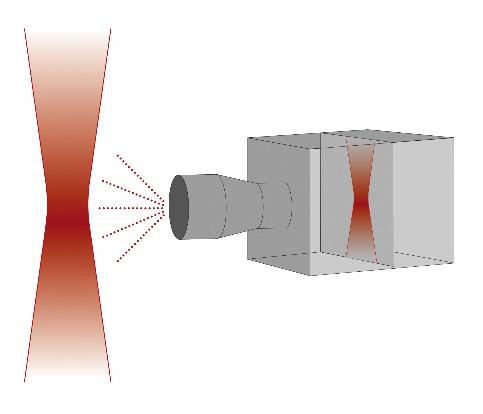
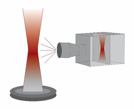
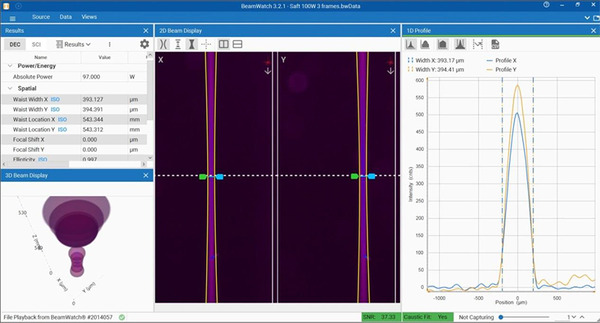
BeamWatch is a technology that produces measurements considered to be essentially equivalent to the measurements made with a scanning slit. In addition, the camera image used in the BeamWatch analysis is constituted of hundreds of individual slit measurements. Each row of data, or lineout, from the image of the caustic is considered to be equivalent to a scanning a slit measurement of the corresponding plane of the caustic. ISO 11146-1 beam propagation measurement requires the acquisition of second moment beam widths. ISO 11146-3:2004(E) provides for alternative measurement methods including the scanning slit method as outlined in section 4.4. Using equations 63 and 69 of ISO 11146-3:2004(E), scanning slit results can be converted to second moment results. In compliance with the ISO standard, the results presented here were calculated according to the conversion described in this section.

Conclusion

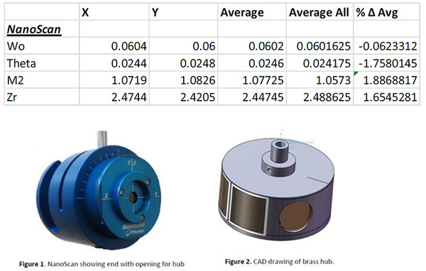
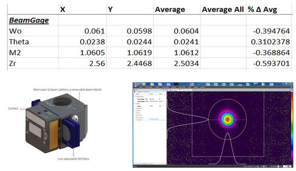
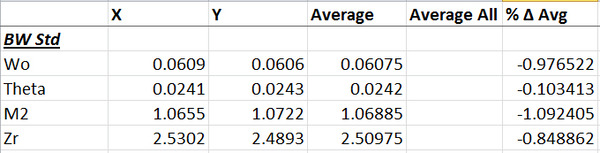
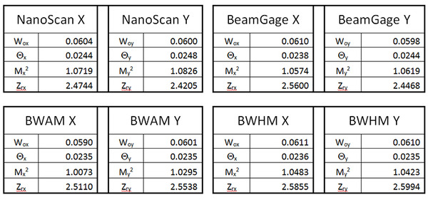
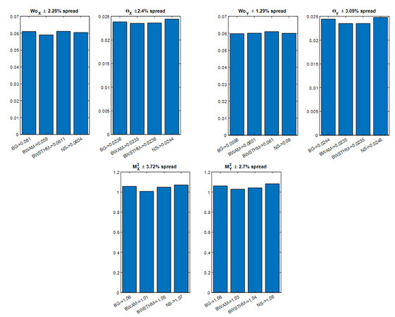
The measurements made with the various non-contact measurement devices based on Rayleigh scattering, BeamWatch and BeamWatch AM, meet all of the requirements of ISO 11146 including second moment beam widths derived from moving slit measurements. The maximum deviation from the mean for each of the three reported results (W0x, W0y, x, y, Mx2, and M²y) is less than 3.75%. There is excellent consistency between the four Ophir instruments tested employing three different technologies and four different calibration standards, giving confidence that BeamWatch based on Rayleigh scattering is a reliable technology for measuring beam quality. Although no official description of employing Rayleigh scatter in the ISO standard measurement of laser beam propagation characteristics exits, high power fiber laser users can be assured that results gained by using the non-contact beam propagation characteristic measurement technology will deliver reliable results that correlate well with measurements acquired with other techniques. In addition to the obvious compatibility of Rayleigh scatter measurements to further the understanding of high-power lasers, these devices benefit from significant advantages.

  • Due to its non-contact nature there is no practical upper power limit for laser that can be measured with this technique.
  • Rayleigh scatter is proportional to the inverse square of its wavelength so that while it is possible to measure the scatter from 1030 – 1080 nm sources, visible and UV sources provide many orders of magnitude more available signal.
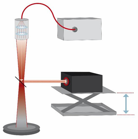
  • No moving parts and no direct interface to the laser beam equates to simplified preventative maintenance and no wear on beam splitter optics.
  • Simplicity of the measurement setup will improve data integrity and comparability of data taken by different persons at different times or locations.

This new application of the Rayleigh scatter phenomenon offers the ability to assure documented performance of the focussed laser beam of high power fiber and IR laser systems with litteraly no upper power limit. By simplifying beam quality measurements, this technology promises that the quality and performance consistency of laser welding, cutting, and heat treating, annealing and additive manufacturing systems can now be assured easily and economically.

Terms and Descriptions

Camera Baseline: The image a camera produces when no energy is impinged on the sensor. The camera baseline contains noise the camera system produces when no external image or energies are presented.

Beam Profiler: A beam profiler is a measurement system that captures an image of a laser beam that represents the cross-sectional intensity distribution of the laser beam at a specific location along the beams propagation axis. Beam profilers are used to measure the size and location of a laser beam. Laser beam profilers can also be used to determine how the cross-sectional energy is distributed. How close to ideal beam distributions such as Gaussian (TEM00), donut mode (TEM*10), or Top Hat modes can be measured with some beam profiler systems.

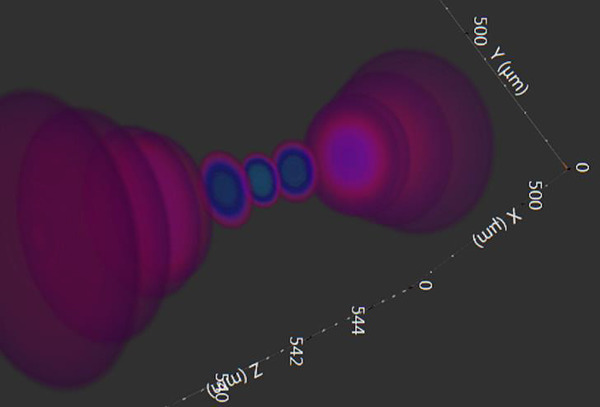
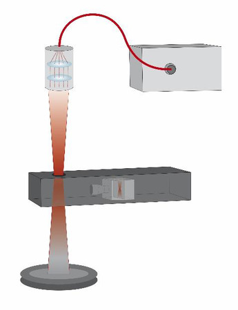
Caustic: The caustic in this definition is the segment of a laser beam that is focused. A focused beam caustic typically contains a number of Rayleigh ranges on both sides of the focal plane or minimum diameter of the beam. In some cases, a caustic is artificially created to measure the propagation characteristics of the laser being tested.

Rayleigh Range: The Rayleigh range is the length of the beam where the diameter changes by the square root of 2. It can also be stated that the cross-sectional area of the beam doubles. The Rayleigh range (or Rayleigh length) is typical measured from the beams waist but can also be stated as multiple Rayleigh lengths along the beam's propagation axis from the waist or focal plane.

Rayleigh Scatter: Rayleigh scatter is scattering of light or other electromagnetic radiation by particles much smaller than the wavelength of the radiation. Rayleigh scattering does not change the state of material. The particles may be individual atoms or molecules.

Second Moment Beam Width: Second Moment and D4sigma are used interchangeably in this document. Each refers to a description of a laser beam width that is 4 times σ, where σ is the standard deviation of the horizontal or vertical distribution. The ISO 11146 requires a Second Moment description of the laser beam width be used for measuring the propagation of a laser beam. The second order moment is defined as:

Single-Mode Fiber Laser Single-mode optical fiber typically has a core diameter between 8 and 10.5 μm and is constructed in such a way that only single transverse modes can propagate through the fiber core. Typically, the core is treated or altered so that light is only transmitted through the core and not the cladding. In addition to benefitting from only transmitting a single optical mode, single-mode fiber also provides little or no degradation of signal and low dispersion.

References

  1. alta™ Medium Power Fiber Lasers, http://www.nlight.net/nlightfiles/file/DatasheetsV2/Fiber%20Lasers/alta/alta%20700W.pdf
  2. BeamGage User Guide, Standard Edition Version 6.x https://www.ophiropt.com/laser--measurement/beam-profilers/products/Beam-Profiling/Camera-Profiling-with-BeamGage
  3. BeamWatch Standard User Notes, Version 3.0, https://www.ophiropt.com/laser--measurement/beam-profilers/products/High-Power-Beam-Profiling/BeamWatch
  4. BeamWatch AM User Note, Document No. 50394-001 Rev C 07/20/2018, https://www.ophiropt.com/laser--measurement/beam-profilers/products/High-Power-Beam-Profiling/BeamWatch-AM
  5. NanoScan v2 Installation and Operation Manual, https://www.ophiropt.com/laser--measurement/beam-profilers/products/Scanning-Slit-Beam-Profiling-with-NanoScan
  6. How to (Maybe) Measure Laser Beam Quality, Professor A. E. Siegman
  7. Edward L. Ginzton Laboratory, Stanford University, Optical Society of America Annual Meeting Long Beach, California, October 1997
Contact Us illustration

Have questions? Require assistance?

Click below to to contact Ophir Photonics and we'll get back with you shortly.

Contact Ophir Photonics