White Paper – Working in the Basement: Measuring Signals Below the Noise Floor with a Lock-In Amplifier

Measuring optical signals in the femtowatt (10-15) to nanowatt (10-9) range can be a daunting task. Signal levels this low are lost in typical detector noise levels and swamped by background light. The noise floor for photodiode detectors operated with a small bandwidth (~10 Hz) is on the order of 1 picowatt (10-12). Further narrowing of the bandwidth by filtering or averaging will only provide a small additional reduction in the noise level.

Author:

Shimon Elstein, Senior Physicist

In order to achieve significant improvements in noise rejection we need to turn to a lock-in amplifier. Lock-in amplifiers can improve noise rejection by 3 orders of magnitude or more. Furthermore, they can provide background signal rejection that is several orders of magnitude higher than the noise rejection.

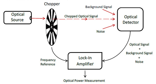
Lock-in amplifiers employ a technique called homodyne detection to attain their outstanding performance. Homodyne detection has two requirements: a) the signal to be detected needs to be modulated and b) a clean reference signal with the same frequency needs to be provided. In the lock-in amplifier, the signal to be measured is multiplied by the reference signal and then integrated over time. This results in an extraordinarily narrow effective bandwidth. Signals at all frequencies that differ by even a small amount from the reference frequency will result in a net integrated value of zero. Since detector noise is “white”, its power is spread across a broad spectrum and the noise amplitude component at the measurement frequency is very low. By confining the measurement to a single frequency, detector noise is reduced drastically. In a similar fashion, background optical signals (primarily DC or line frequency) are similarly rejected by the lock-in amplifier.

The key to high performance with a lock-in amplifier is maintaining a precise match between the modulation frequency of the signal to be measured and the frequency of the reference signal. In optical applications this precise match is readily built in to the architecture. Many low level optical signals that need the benefits of a lock-in amplifier are DC or very low frequency. In these applications, an optical chopper is used to modulate the signal.

An optical chopper is simply a spinning disk that is divided into vanes and windows. The chopper disk is positioned in the optical beam path so that as it spins the beam alternately passes through the windows and is blocked by the vanes.

The size of the beam should be smaller than the width of the vanes / windows in order to achieve 100% modulation.

Figure 1. Typical Optical Chopper Disk

In optical choppers, the reference signal is easily provided by using an optical interrupt switch to sense the rotation of the vanes and windows. The optical interrupt switch can be located at any radial location on the disc that doesn’t conflict with the passage of the optical beam. The reference signal provided in this manner will be a precise frequency match for the optical signal to be measured. For optimal performance it is still important to tightly control the disc rotation speed to minimize jitter and other artifacts. A high degree of uniformity in the disc geometry is also critical.

In setting up the system for use, the chopper should be as close as possible to the optical signal source so that the modulation is applied exclusively to the signal of interest and not to any unwanted background signals that may be present.

Figure 2. Lock-In Measurement Schematic

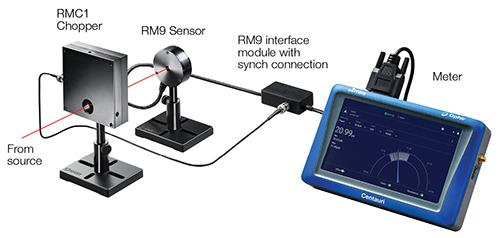
Ophir’s RM9 family of sensors incorporate a compact, dedicated lock-in amplifier, an optical chopper and a selection of sensitive detectors in an easy to use system for measuring ultra-low signal levels even in the presence of much larger background noise.

Detector types include:

Figure 3. Ophir RM9 System

This sensor family provides high performance for a wide range of demanding applications such as spectroscopy, THz detection, free space gas analysis, atmospheric studies, Raman scattering, and many others.

Contact Us illustration

Have questions? Require assistance?

Click below to to contact Ophir Photonics and we'll get back with you shortly.

Contact Ophir Photonics