Select the Right Laser Power Sensor by Asking the Right Questions

The selection of an appropriate sensor to measure the power of a laser seems to be a simple and straightforward process. The sensor technology doesn’t seem to be too complex, the physical setup of the sensor seems easy enough. Yet, more often than not, the sensor turns out to NOT be the right one. As a result, inaccurate measurements are obtained, the sensor exhibits premature failure, and costly full disc replacement and recalibration are required.

Author:

Dick Rieley, Field Sales Engineer III, Mid-Atlantic Region, Ophir-Spiricon

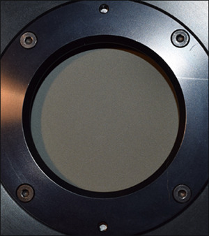
Figure 1. Disc Condition: Clean, free of any pits or blemishes — accurate measurements.

The first question that must be asked is, “What is the wavelength of the application, or does the application require coverage of a range of wavelengths?” This initial question is essential as some sensors are considered broadband (suitable for 0.19 to 20 um and beyond ). Others are highly specific to just UV or a very narrow band, such as 0.19 to 2.2 um. What this means is that low power sensors, such as photodiodes measuring from pW to 2-3 watts, are wavelength specific. The wavelength at which the measurement needs to be taken must be designated in the supporting display meter. Otherwise the measurement is relative at best and not accurate to the tolerances of the sensor.

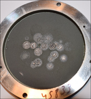
Figure 2. Disc Condition: Damaged, heavily pitted with coating ablated — inaccurate measurements, must be replaced.

One peculiar application that typically requires a low power photodiode sensor, is the measurement of white light. In this application, all the wavelengths are present so no one wavelength can be selected. However, by its very nature, this measurement is relative not absolute.

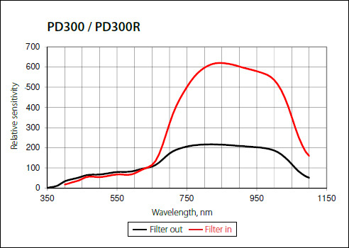
Figure 3 displays the absorption curve of a typical photodiode and demonstrates the importance of selecting the wavelength of the needed measurement; if an incorrect measurement algorithm is selected, it will result in an inaccurate measurement.

Figure 3. Typical broadband absorption curve.

In higher power sensors, it is typical only to select a range of wavelength to ensure the sensor is set for its best accuracy and to accommodate the absorption curve of the best sensor selected.

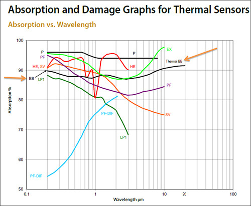
Figure 4 shows the typical broadband (thermal BB) absorption curve, along with a variety of other specialized sensors. This BB curve demonstrates the relative flatness of the its absorption; only a range of wavelengths typically needs to be selected.

Figure 4. Absorption and damage graphs for thermal sensors.

A second key question to ask is, “What is the range of powers the sensor needs to measure?” The selection of a sensor when it comes to its power range is one of the more critical in that the incorrect selection will most likely result in a damaged sensor. For example, when measuring a 10 W laser source, DO NOT select a sensor that has a range from mW to 10 W. This can result in pushing the sensor beyond its capability and again, damage can occur. In this case, select a sensor where 10 W represents the middle of the range, such as a 30w sensor that measures from mw’s to 30 W. Damage will always occur when pushing a sensor over its limit. Damage will NEVER occur when too little power is used on the sensor.

A third key question to ask is “What is the size and shape of the beam to be measured when targeted onto the sensor?” The power density of the beam is the most destructive element causing disc failure. It is important to know or even to estimate the size of the beam at the power measurement point. Using a beam profiler, burn paper, or a visual indication will help. First, the power measurement of the beam when used on a focused, non-collimated beam should NOT be attempted. Typically the power density of this type of measurement is too great for any disc and damage will occur, if not immediately, it will over time with repeated efforts. The position of the sensor needs to be located in the beam path where the power density is within the acceptable limits of the disc specifications. This means positioning the sensor in the beam path before or after the focal point. The other key aspect of the beam is its shape. Does the beam possess a Gaussian or TopHat shape? This is equally important to the location of the sensor in the beam path.

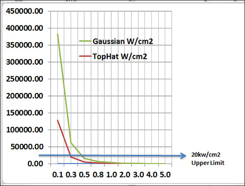
Figure 5 demonstrates the dramatic effect of power density between a Gaussian vs a TopHat beam and shows the effect of power density when the beam size is reduced. This chart plots nine (9) different beam sizes from 0.1 to 5 mm, showing the difference in Power Density between a TopHat Beam and a Gaussian Beam. Generally, the Power Density of a Gaussian beam is twice that of TopHat Beam.

Figure 5. Differences in power density for TopHat beam vs Gaussian beam. Beam Diameter is on the X Scale, Power Density in W/cm2 is on the Y Scale.

Most sensors for power measurement can handle up to 20 kW/cm2, shown in the Blue Line at the bottom of Figure 5. However, if you try to measure a beam diameter less then 0.5 mm for a Gaussian beam, or less than 0.3 mm for a TopHat beam, damage will occur.

Power density is one of the most important criteria of a laser beam when selecting a power sensor. If a calculation program is not available through your vendor, the TopHat formula is:

Average Power / (Beam Diameter)2 x 78.5/10,000.

For example: 10 / (5m m)2 x 78.5/10,000 = 51 W/cm²

The formula for a Gaussian Beam (1/e² measurement) is:

2 x Average Power / (Beam Diameter)2 x 78,5/10,000

For example: 2 x 10 / (5 mm)2 x 78.5/10,000 = 102 W/cm²

For typical power measurement sensors, keep in mind these three question: what is the wavelength of the beam, what is the power range of the beam, and what are the beam shape and size on the detector surface. With this information in hand, check these calculations against the specifications of the selected sensor to ensure the requirements of the application are within the specification of the sensor.

Contact Us illustration

Have questions? Require assistance?

Click below to to contact Ophir Photonics and we'll get back with you shortly.

Contact Ophir Photonics