仕様
- 340-1100nm
- 45μm - 23mm
- GigE
- CMOS, Global shutter
- CW,パルス
- 23mm x 23mm
- 5120 x 5120
- 4.5μm
- 44.6 dB
- 4.5 fps (10 bit mode)
- CE, UKCA, China RoHS
製品概要
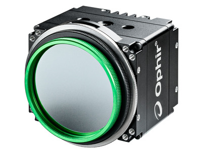
ラージフォーマット SP504S GigE CMOS、グローバル シャッター高分解能カメラは、次のバージョンのソフトウェアで使用できます。
-
BGP-G-SP504S
SP90618Power Supply 12V, Gigabit Ethernet Cable CAT6E 5 Meter and 3 ND filters (1.0, 2.0 & 3.0 optimized for use in the region of 400-700nm; ND 3.0 filter is installed in the input aperture of the camera)
御見積り -
BeamGage Training DVD
SP90429How to become a great user of the world’s most powerful laser beam analysis software https://youtu.be/w9JkKIXcF5s
御見積り
Documentions
FAQ
カメライメージ品質について
Camera Defects Policy
Ophir-Spiricon, LLC (OSL) is a supplier of laser beam analysis tools that employ commercial-industrial solid-state cameras. OSL attempts to supply cameras with as few pixel defects as possible. OSL tests for and corrects defective pixels that may have an adverse effect when used for its intended purpose. OSL does not guarantee that a supplied camera will be defect free, or that they will remain defect free during its normal lifetime and under normal use.
It is not uncommon for modern megapixel camera imagers to develop point defects as they age, even when not subjected to abuse. Imagers without windows often experience point defects at rates typically greater than imagers with their cover glass left in place. Point defects can also appear more frequently when operating at higher rather than lower ambient temperatures, and higher relative humidity. Such defects can occur even when the camera is in storage and not being used.
Cameras supplied by OSL will be certified for use in laser beam analyzer applications. When defects occur, the ability to make certain measurements under certain conditions may be compromised. However, depending upon the nature of the defect, most measurement can still be performed without loss of accuracy. In some instances the effects of defects can be eliminated or significantly reduced by adjusting the manner in which the camera is being employed.
Ophir-Spiricon, LLC offers a camera recertification service. This service can help to extend the useful life of your camera and correct some point defects that may show up over time. This service can not correct cameras with serious laser damage or imager degradation. Whenever possible OSL will restore the camera to our "as new" level of certification; and if not possible, we will indicate to the user how to avoid areas of the imager that may not perform to "as new" standards.
Defects, Solutions and Workarounds
The following list contains examples of typical camera point defects that may occur over time, and suggested methods of compensating for them if they are troublesome:
Defect type | Description of the Problem | Recommended Solution See Note 1 below |
Bright Pixel | Pixels with this defect will indicate being illuminated even when no signal is present. These are the most troublesome when attempting to make accurate peak fluence and peak fluence location measurements because they represent a false signal. Most other measurements are not adversely affected by this type of defect. This type of defect is screened for during our regular camera inspection process. All pixels that exceed a set limit are corrected, if possible, before the camera ships. See Note 1 below. Our QA department will often reject cameras if the pixel can not be corrected and it exceeds our acceptance criteria. |
|
Twinkling Pixel | This is an intermittent version of the Bright Pixel defect. These often appear as the camera warms up. May disappear if the camera is run in cooler environments. Usually predicts a pixel that will soon be a permanently bright pixel defect.
These are the hardest to detect and as such may get past our camera inspection process. |
Same as above.
If returned to OSL to be corrected please send a full frame data file showing the pixel as it is malfunctioning. This will aid in our ability to find and fix it. |
Dark Pixel | Dark pixels have low responses compared to the amount of illumination that they receive. Isolated instances of these types of defects do not pose a serious beam analysis problem and they are generally not in need of correcting. | This type of defect will not significantly impact a beam measurement result unless the beam is very very small and the defect falls inside of the beam profile. Reposition the camera to remove the defective pixel from the measurement region. |
Dead Pixel | Dead pixels have no response at all and may output a raw pixel value of zero (0) counts. This type of defect is screened for during our regular camera inspection process. All pixels that exceed a set limit are corrected, if possible, before the camera ships. | This type of pixel may create a warning message when performing Ultracal operations. Ignore the warning and proceed as in the Dark Pixel case described above. |
Dark Clusters | These dimmer than normal clusters involving about a dozen or fewer pixels are often caused by dust particles and can usually be removed by cleaning of the imager. Sometimes these can be very difficult to impossible to remove. In the latter case they are may be melted into imager
If this is the result of laser damage then imager replacement is the only solution. |
These usually do not cause serious measurement problems and can be treated with the Dark Pixel workaround described above. They can sometimes be dislodged with very gentle puffs of dry air. If you return a camera to be re-certified we have a few special methods for cleaning these, but success is not 100% guaranteed. |
Regions of non-uniform response | When large areas of an imager yield reduced signal levels this usually indicates laser damage. Long term exposure to ultraviolet radiation or overexposure to high laser power or peak energies are common causes. | This type of degradation is not repairable and either the camera or the camera imager must be replaced. |
Note 1: The following camera models can be re-certified and can have bad pixels corrected:
GRAS20, SP620, L11058, L230, Pyrocam III, Xeva
Each of the above cameras will have a maximum number of pixels that can be corrected. Once this limit is exceeded the camera imager or the camera must be replaced in order to meet OSL "as new" certification standards. If a large cluster of defective pixels appear, then bad pixel correction may not be able to repair the defect. The following cameras do not have, or have very limited, bad pixel correction capabilities:
SCOR20, SP503, FX50, FX33, FX33HD
SP503UやSP620UカメラのROIについて
The initial release of the SP503U and SP620U cameras did not have the ROI feature enabled. Those cameras that do not have the ROI feature enabled will need to be returned for upgrading both hardware and firmware, and the latest version of software will need to be installed, which is available at;
https://www.ophiropt.com/laser-measurement-instruments/beam-profilers/se...
SP503UやSP620Uカメラのフォトダイオードトリガ
With the introduction of BeamGage the capability of using the built in photodiode trigger in the SP camera series is now available. However, some customers may not know how to use it or that they even had this capability.
With the recently released BeamGage version 5.4 this capability is now available. Some cameras may need to have their firmware upgraded where others just need to update to the latest version of BeamGage. To see if your camera has the latest firmware make sure you are using BeamGage 5.4 and connect your camera to the computer. Launch BeamGage and when it opens click on the Source tab. Then click on the Tools button and in the drop down list select Firmware Info. This will turn on a new section of the ribbon bar that will show the Current Version of firmware installed in the SP series of cameras. Depending on your computer screen resolution you may need to click on this section of the ribbon bar to expand this area to be able to see this information. For the SP620U it needs to be running version 207 or higher and for the SP503U it needs to be running version 305 or higher.
If by chance your camera's firmware is not a high enough version, you can easily return your camera to Ophir-Spiricon to be reprogrammed with the latest firmware to enable this capability. Please send an e-mail to Service@US.Ophiropt.com with the subject line of "RMA for camera firmware upgrade". An RMA Check List form will be e-mailed back to you to complete with your information and the S/N of your camera. Once we receive this form back we will e-mail you an RMA number and shipping instructions for sending back your camera to have the firmware upgraded to enable the built in photodiode trigger.
This built in photodiode trigger is a great option to have if your source is pulsed and you do not have an electronic sync signal to be able to sync the data acquisition of the camera to the source. This build in photodiode works for pulsed sources up to 1 KHz to be able to isolate one pulse per frame.
To enable this function, after making sure the firmware is the most current, all you need to do is click on the Source tab and then in the Trigger section drop down the Trigger box and select On-Board Photodiode. You will get a message that pops up stating "Make sure that the laser is turned off and lighting conditions in the room are similar to those that will exist during the laser measurement." When you click OK you will get a new box that comes up saying "Photo-diode calibration complete! You may now trigger the camera from the on-board photo-diode." Click OK or allow it to time out which will automatically click the OK button. Now the camera will wait for a laser pulse to illuminate the built in photodiode sensor to advance to the next frame.
Please note when using our LBS-300 beam sampler/attenuator option you may need to mount the camera inverted so the built in photodiode sensor will be uncovered from behind the mechanical housing of the LBS-300 assembly.
If you have any questions, or we can be of any assistance, please don't hesitate to contact our Service Department at:
Ophir-Spiricon
435-753-3729
Service@US.Ophiropt.com
ビームプロファイル計測可能な最大ビーム径はどのくらいですか?
The largest laser beam we have measured has been 3 meters. This was done with the addition of a cctv lens and then a spatial calibration to give the equivalent pixel size with the lens at the distance we observed the laser. We achieved this by imaging a target that the laser fell upon. The target was in motion slightly to eliminate any speckle. Most applications the beams are less the 10mm, these can be accommodated by large array cameras and attenuation. When a beam gets larger say up to 25mm a reducing telescope can be used to bring it down to size to fit on the array. Our largest array currently is 26x39mm and has a USB interface
閉じる動画

オフィ−ル社のレーザパワーセンサを接続してどのようにパワー/エネルギ測定をするかをご紹介します。

カメラベースのビームプロファイラシステムのセットアップ方法を工業用シングルパルスレーザ溶接システムを例にご紹介します。

BeamGageビームゲージ・ソフトウェア/プロフェッショナル版とエンタープライズ版のご紹介です。LabView,Visual Basic、C++,C#に対応、動画ではLabViewのデモンストレーションについて説明します。
BeamGageビームゲージ・チュートリアル:CCDカメラの取り扱い方法、ソフトウェアのインストール、BeamGageソフトウェアの紹介、マニュアルへのリンク付きヘルプシステム、BeamGageソフトウェアの初期設定
Support
同一条件での比較:レーザビームアプリケーションに最適なカメラ技術はどれですか?
レーダーガン/LIDAR
BeamGageビームゲージ・プロフェッショナル版でのマルチビーム計測
アクセサリ
-
The Optical Camera Trigger is an optical sensor that detects pulsed light sources and generates outputs to trigger a camera. The front aperture of the Optical Trigger must be directed at a light source that provides the necessary properties for trigger activation. (e.g. a laser flash lamp, a pick-off source from the main laser beam, or similar).
-
The LBS-100 system that is not as compact as the LBS-300s above but has
-
The LBS-400 beam sampler attachment for Pyrocams and large format Beam Profilers allows measuring UV, NIR or IR wavelength laser beams with diameters up to 1 inch (25.4mm) and powers ranging from 10mW to ~500W(1). The output beam preserves the polarization of the original beam.
-
The LBS-300s beam splitter attachment for C-mount, CS-mount, or Ophir mount cameras allow you to measure laser beams with diameters up to 15mm and powers ranging from 10mW to ~400W(1). The beam sampler is designed so that the preferential polarization selection effect of a single wedge is cancelled out and the resulting beam image is polarization