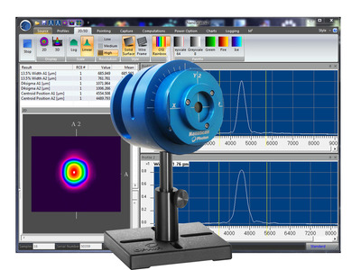
NanoScan 2s Ge/9/5
This NanoScan scanning-slit profiling system accurately captures and analyzes wavelengths from 700nm - 1800nm with its Germanium detector. It features an aperture size suitable for most beams, near real-time data capture rates, an optional power measurement feature, and operates in CW or kHz Pulsed modes which makes it ideal for comprehensive analysis of IR and NIR lasers.
- Beam Sizes of 20µm to ~6mm
- Power Levels of ~10nW to ~10W
- USB 2.0 Interface
- NanoScan Standard or Professional software included
Specification
- 700-1800nm
- 20μm - ~6mm
- USB 2.0
- Germanium
- CW, Pulsed >25kHz
- ~10nW - ~10W
- 5µm
- 9mm
- 83mm
- CE, UKCA, China RoHS
Ordering
The Germanium NanoScans are available with the following versions of software. CLICK HERE for more information on the different versions of NanoScan software.
-
NS2s-Ge/9/5-STD
PH00460NanoScan2s Ge Detector 9mm Aperture 5 µm slits. High-resolution head featuring Germanium detector, 63.5mm diameter head with rotation mount, 9mm entrance aperture, and matched pair of 5 µm wide slits. Use from 700nm to 1.8µm wavelength
Request a Quote -
NS2s-Ge/9/5-PRO
PH00468NanoScan2s Ge Detector 9mm Aperture 5 µm slits. High-resolution head featuring Germanium detector, 63.5mm diameter head with rotation mount, 9mm entrance aperture, and matched pair of 5 µm wide slits. Use from 700nm to 1.8µm wavelength
Request a Quote
Software includes ActiveX automation feature. -
NSv2 STD to NSv2 PRO Software Upgrade
PH00417Upgrade NanoScan v2 Standard version software to the PRO version. This upgrade opens the NanoScan automation feature for those users wanting to integrate or develop their own interface using Visual Basic for Applications to embed into such applications as LabView. Return scanhead to factory.
Request a Quote
Documentions
Download NanoScan Standard
NanoScan Standard is our full-function software with a extensive set of NIST traceable ISO beam width and roundness, beam position, and M2 measurements and a customizable user interface with the ease-of-use and flexibility that customers have come to expect.Download NanoScan Professional
NanoScan Professional has all of the functionality that NanoScan Standard includes. NanoScan Professional supports all of our scanning slit profilers, but includes an automation interface written in ActiveX to push data to your custom applications.
Drawings
FAQ
Where is the detector in the NanoScan?
The detector is mounted internal to the NanoScan behind the rotating slits. This position is not important to the measurements. The measurement plane is the scan plane of the slits, which is nominally 0.74mm +/-0.025 mm from the Reference Surface on the front of the NanoScan. Please refer to the mechanical drawings in Appendix B of the NanoScan Operational Manual.
CloseWhy is the silicon NanoScan not recommended for 1064nm beam measurements?
The silicon detector is very transparent to NIR light >1000nm. If it is used for measuring these beams, you will often see a tailing profile, because the signal does not decay fast enough. This will lead to erroneous results. We recommend using the germanium, or if there is enough power, the pyro electric detector for these wavelengths.
CloseAfter setting up the NanoScan profiler and acquiring the beam, the profile is bouncing back and forth.
Won't the NanoScan slit diffract the beam?
Can I get closer to the front of the NanoScan V2 since it has a new C-Mount adapter ring?
The NanoScan V2 product is great for looking at focused spots, but sometimes the C-Mount ring that is on the front can get in the way mechanically. By removing the three retaining screws it will allow you to remove this ring so you can get mechanically closer to the front of the NanoScan V2. Care should be used when removing these screws and the ring so something does not fall down inside the input aperture of the NanoScan V2. It is recommended that if you are going to remove the C-Mount ring that you invert the NanoScan V2 so it is looking at the floor and then remove the screws and the C-Mount ring to allow gravity to work in your favor and pull them away from the input aperture.
CloseMy NanoScan system is giving me an error that says” The selected speed could not be set within 0.01%!” What does this mean?
This means that the motor is not able to set the rotation speed to within 0.01% precision. This typically means that the motor is wearing out, or that something is causing the motor to not be able to rotate at a constant speed. This typically requires that the system come back to the factory for inspection and repair.
This could also mean that you are running the wrong software. If the NanoScan does not have a Mini USB connection on the head, it should not be run on NanoScan 2.4.X software. It should be run on version 2.1 SR1 software.
CloseCan multiple NanoScans be run from the same PC, or can you connect multiple NanoScans and select the one you want to run?
Videos

This tutorial is presented by Ophir-Spiricon sales engineers - the experts in the field of measuring lasers and in helping you get the most out of your laser beam.

Is your laser's beam profile shaped correctly for your application?
This video teaches the fundamentals of laser beam profiles and discusses the benefits of profiling your laser beam.
Several case studies are presented showing before and after laser beam profiles.
See for yourself how easy it is to use a NanoScan to measure your laser beam. This 3-minute video shows the NanoScan profiling both a HeNe and a high power laser.
Support
Making High Power Measurements with Little to No Attenuation
Upgrading NS v2 software from Standard to Professional
White Paper – ISO compliance of non-contact, real-time beam analysis
Laser forensics: The invisible, revealed and measured
Measuring Laser Position & Pointing Stability
Imaging UV light with CCD Cameras
Understanding Dynamic Range…The Numbers Game
Laser Beam Measurement Vocabulary
Measurement of Mode Field Diameters of Tapered Fibers and Waveguides for Low Loss Components
The Challenge of Focus Shift in High Power Laser Material Processing
Accessories
-
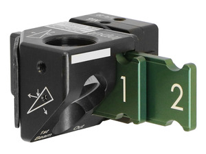
The LBS-300s beam splitter attachment for C-mount, CS-mount, or Ophir mount cameras allow you to measure laser beams with diameters up to 15mm and powers ranging from 10mW to ~400W(1). The beam sampler is designed so that the preferential polarization selection effect of a single wedge is cancelled out and the resulting beam image is polarization