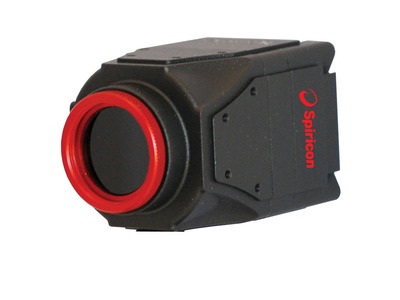
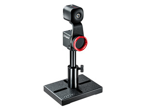
LT665-1550 Beam Profiling Camera

LT665-1550 Beam Profiling Camera

USB 3.0 Phosphor Coated Large Format Silicon CCD High Resolution Camera with BeamGage
Description: 

The LT665-1550 camera accurately captures and analyzes wavelengths from 1440nm - 1605nm. It features a compact design, wide dynamic range, unparalleled signal to noise ratio, and a 1" format that makes it ideal for large beam NIR laser and telecom mode field analysis.

  • 12.5mm x 10.0mm active area with an effective 60µm pixel pitch
  • Adjustable Gain levels and programmable electronic shutter
  • BeamGage Standard or Professional software included

Specification

  • 1440-1605nm
  • 600μm - 9.8mm
  • USB 3.0
  • Phosphor-Coated Silicon CCD
  • CW, Pulsed
  • 12.5mm x 10.0mm
  • 2752 x 2192
  • 50μm
  • ~30 dB
  • 27 fps
  • CE, UKCA, China RoHS
Need help finding the right beam profiler? Try our Beam Profiler Finder

Ordering

The large format phosphor-coated LT665 USB 3.0 silicon CCD high resolution camera is available with the following versions of software.

Learn more about the different versions of BeamGage

  • BGS-USB3-LT665-1550

    SP90384

    BeamGage Standard Edition software, software license, 1 inch format 2752x2192 pixel camera with 17.5mm C mount CCD recess. Phosphor coated 1550nm sensor. Comes with USB 3.0 cable and 3 ND filters

    Request a Quote
  • BGP-USB3-LT665-1550

    SP90385

    BeamGage Professional Edition software, software license, 1 inch format 2752x2192 pixel camera with 17.5mm C mount CCD recess. Phosphor coated 1550nm sensor. Comes with USB 3.0 cable and 3 ND filters

    Request a Quote
  • BGS TO BGP UPGRADE

    SP90233

    Upgrade BeamGage Standard Edition to Professional Edition. Requires a new camera key to activate.

    Request a Quote
  • BeamGage StandardBeamGage Standard
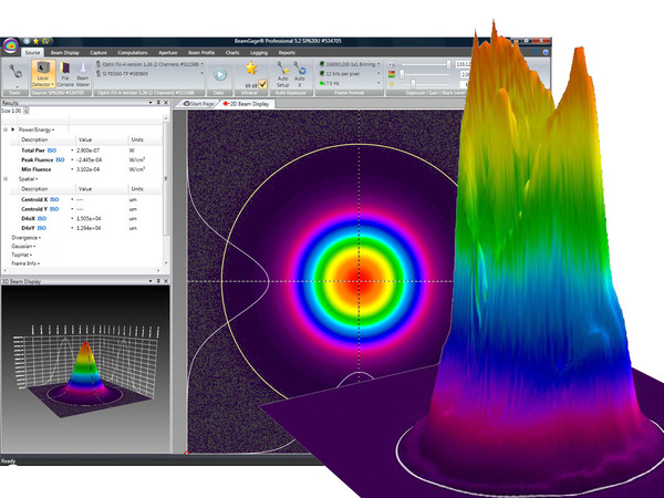
    BeamGage Standard is our full-function software with an extensive set of ISO quantitative measurement, our patented Ultracal™ algorithm for the highest accuracy measurements in the industry.
  • BeamGage ProfessionalBeamGage Professional
    BeamGage Professional has all of the functionality that BeamGage Standard includes. BeamGage Professional supports all of our beam profiling cameras, includes window partitioning to allow analysis of multiple beams on a single camera, and includes an automation interface written in .NET to push data to your custom applications.

FAQ

Camera Image Quality – We frequently get asked about image quality as it relates to dead or bad pixels in the imager array. These questions most generally fall into one or more of these categories. Will my camera have any bad pixels? Do bad pixels affect my laser profile measurement? Can bad pixels be corrected? If I have some bad pixels what can I do about it? Will my camera performance change over time? All and more of these concerns are explained in our Camera Defects Policy document.

Camera Defects Policy
Ophir-Spiricon, LLC (OSL) is a supplier of laser beam analysis tools that employ commercial-industrial solid-state cameras. OSL attempts to supply cameras with as few pixel defects as possible. OSL tests for and corrects defective pixels that may have an adverse effect when used for its intended purpose. OSL does not guarantee that a supplied camera will be defect free, or that they will remain defect free during its normal lifetime and under normal use.

It is not uncommon for modern megapixel camera imagers to develop point defects as they age, even when not subjected to abuse. Imagers without windows often experience point defects at rates typically greater than imagers with their cover glass left in place. Point defects can also appear more frequently when operating at higher rather than lower ambient temperatures, and higher relative humidity. Such defects can occur even when the camera is in storage and not being used.

Cameras supplied by OSL will be certified for use in laser beam analyzer applications. When defects occur, the ability to make certain measurements under certain conditions may be compromised. However, depending upon the nature of the defect, most measurement can still be performed without loss of accuracy. In some instances the effects of defects can be eliminated or significantly reduced by adjusting the manner in which the camera is being employed.

Ophir-Spiricon, LLC offers a camera recertification service. This service can help to extend the useful life of your camera and correct some point defects that may show up over time. This service can not correct cameras with serious laser damage or imager degradation. Whenever possible OSL will restore the camera to our "as new" level of certification; and if not possible, we will indicate to the user how to avoid areas of the imager that may not perform to "as new" standards.

Defects, Solutions and Workarounds
The following list contains examples of typical camera point defects that may occur over time, and suggested methods of compensating for them if they are troublesome:

Defect type Description of the Problem Recommended Solution
See Note 1 below
Bright Pixel Pixels with this defect will indicate being illuminated even when no signal is present. These are the most troublesome when attempting to make accurate peak fluence and peak fluence location measurements because they represent a false signal. Most other measurements are not adversely affected by this type of defect. This type of defect is screened for during our regular camera inspection process. All pixels that exceed a set limit are corrected, if possible, before the camera ships. See Note 1 below. Our QA department will often reject cameras if the pixel can not be corrected and it exceeds our acceptance criteria.
  1. Ultracal/baseline correction will subtract out the defective pixel.
  2. Reposition the camera to remove the defective pixel from the measurement region and employ a manual aperture to isolate the pixel from the area of interest.
  3. Return the camera to OSL to have the bad pixel corrected and the camera re-certified.
Twinkling Pixel This is an intermittent version of the Bright Pixel defect. These often appear as the camera warms up. May disappear if the camera is run in cooler environments. Usually predicts a pixel that will soon be a permanently bright pixel defect.

These are the hardest to detect and as such may get past our camera inspection process.

Same as above.

If returned to OSL to be corrected please send a full frame data file showing the pixel as it is malfunctioning. This will aid in our ability to find and fix it.

Dark Pixel Dark pixels have low responses compared to the amount of illumination that they receive. Isolated instances of these types of defects do not pose a serious beam analysis problem and they are generally not in need of correcting. This type of defect will not significantly impact a beam measurement result unless the beam is very very small and the defect falls inside of the beam profile. Reposition the camera to remove the defective pixel from the measurement region.
Dead Pixel Dead pixels have no response at all and may output a raw pixel value of zero (0) counts. This type of defect is screened for during our regular camera inspection process. All pixels that exceed a set limit are corrected, if possible, before the camera ships. This type of pixel may create a warning message when performing Ultracal operations. Ignore the warning and proceed as in the Dark Pixel case described above.
Dark Clusters These dimmer than normal clusters involving about a dozen or fewer pixels are often caused by dust particles and can usually be removed by cleaning of the imager. Sometimes these can be very difficult to impossible to remove. In the latter case they are may be melted into imager

If this is the result of laser damage then imager replacement is the only solution.

These usually do not cause serious measurement problems and can be treated with the Dark Pixel workaround described above. They can sometimes be dislodged with very gentle puffs of dry air. If you return a camera to be re-certified we have a few special methods for cleaning these, but success is not 100% guaranteed.
Regions of non-uniform response When large areas of an imager yield reduced signal levels this usually indicates laser damage. Long term exposure to ultraviolet radiation or overexposure to high laser power or peak energies are common causes. This type of degradation is not repairable and either the camera or the camera imager must be replaced.

Note 1: The following camera models can be re-certified and can have bad pixels corrected:
GRAS20, SP620, L11058, L230, Pyrocam III, Xeva
Each of the above cameras will have a maximum number of pixels that can be corrected. Once this limit is exceeded the camera imager or the camera must be replaced in order to meet OSL "as new" certification standards. If a large cluster of defective pixels appear, then bad pixel correction may not be able to repair the defect. The following cameras do not have, or have very limited, bad pixel correction capabilities:
SCOR20, SP503, FX50, FX33, FX33HD 

Was this FAQ helpful to you? yes no
Close

How come I can't use the Cameras Region Of Interest (ROI) Feature in my SP503U or SP620U Camera?

The initial release of the SP503U and SP620U cameras did not have the ROI feature enabled. Those cameras that do not have the ROI feature enabled will need to be returned for upgrading both hardware and firmware, and the latest version of software will need to be installed, which is available at;
https://www.ophiropt.com/laser-measurement-instruments/beam-profilers/se...

Was this FAQ helpful to you? yes no
Close

Why is an anti-reflection coated window required with the Pyrocam III?

The Pyrocam III needs a window for protection against foreign objects entering the camera, and destroying the crystal. This could happen by someone poking a brush or Q-tip to clean off lint, etc. The window also protects the sensor from the effects of humidity. The window must have anti-reflection coating, or the two surfaces of the window will create interference fringes from a collimated light source which show up on the sensor as ripples in the beam. With anti-reflection coating the reflections, and thus the interference fringes, are minimized, and the sensor sees only the beam energy.

Was this FAQ helpful to you? yes no
Close

Videos

Video Series: BeamGage Tutorials Video Series: BeamGage Tutorials
Fundamentals of Laser Measurement & Beam Profiling Fundamentals of Laser Measurement & Beam Profiling Fundamentals of Laser Measurement & Beam Profiling

Is your laser's beam profile shaped correctly for your application?
This video teaches the fundamentals of laser beam profiles and discusses the benefits of profiling your laser beam.
Several case studies are presented showing before and after laser beam profiles.

Measuring Laser Focus Spot Size in an industrial Medical Device Application Measuring Laser Focus Spot Size in an industrial Medical Device Application Measuring Laser Focus Spot Size in an industrial Medical Device Application

This step-by-step tutorial will show you how to set up a camera-based beam profiling system on an industrial single-pulse laser welding system.
It will also demonstrate for you how to simultaneously analyze the laser's focused spot, measure the laser's energy per pulse, and measure its temporal pulse shape.

How to Design Your Perfect Laser Beam with BeamMaker How to Design Your Perfect Laser Beam with BeamMaker How to Design Your Perfect Laser Beam with BeamMaker

BeamMaker helps engineers, technicians, and researchers understand a beam's modal content by subtracting theoretically generated modes from real beam measurement data. Derive a perfect beam profile by specifying the mode, size, width, height, intensity, angle, and noise content - then comparing it to theoretically derived measurements. The end result is knowledge about how much the real beam varies from the desired beam.

Watch the BeamGage Tutuorials, including tips on handling your CCD camera, software install, introduction to the BeamGage user interface, the context-sensitive help system and user manual, customizing your reporting environment, and configuring BeamGage to display specific laser measurements.

Support

Tutorials and Articles

White Paper – Apples to Apples: Which Camera Technologies Work Best for Beam Profiling Applications, Part 1

In 1997, Dr. Carlos Roundy, founder and president of Spiricon Inc., presented a paper at the 4th International Workshop on Lasers and Optics Characterization in Munich Germany. This paper was based on work that was carried out at Spiricon in the mid 90’s. At the time new insights were being presented on how to characterize a laser beam. Previous definitions were somewhat simplistic and most often were driven by customers telling us how they wanted the beam measured. Read more...

LIDAR Guns, Accuracy, and Speeding Tickets

Anyone who has driven a vehicle has encountered a Light Detection and Ranging (LIDAR) system in action. Some of you have even found out how much it can cost in terms of speeding fines! Let’s take a closer look behind the scenes. How do we know the detector is working? Read more...

BeamGage Professional partitions with multiple beams on one display with individual results.

The Partition feature, available in BeamGage Professional, allows subdividing the camera imager into separate regions, called partitions, and which can then compute separate beam results within each partition. Read more...

Using the built in photodiode trigger on the SP620U and SP503U cameras.

With the introduction of BeamGage the capability of using the built in photodiode trigger in the SP camera series is now available. However, some customers may not know how to use it or that they even had this capability.  Read more...

Imaging UV light with CCD Cameras

Is it possible to image a UV laser with a Silicon Sensor CCD camera offered by Ophir-Spiricon? The answer is yes, but the direct UV light ablates Silicon CCD chips over time. The ablation is cumulative and depends on the intensity, the wavelength, and the duration of the light on the sensor. The best choice for imaging UV light without damage is to avoid directly imaging the beam on the CCD sensor by using an UV image converter... Read more...

Understanding Dynamic Range…The Numbers Game

There is a fair amount of confusion caused by the reporting of dynamic range of beam profilers. The purpose of this applications note is to explain some of the terminology used in the discussion of this parameter by both Ophir- Spiricon and other suppliers of beam profilers. DefinitionDynamic Range is the ratio of the largest measurable signal to the smallest measurable signal. The smallest measurable signal is typically defined as that equal to the noise level, or alternatively the “Noise Equivalent Exposure” or that point where the Signal-to-noise ratio (SNR) is 1. To Read more...

The Focal Length Divergence Measurement Method

The Focal Length Divergence measurement method is based upon the beam width of a focused beam’s spot size and the focal length of the focusing optic. The Focal Length Divergence method provides a means for finding the far-field beam divergence at any point in the beam propagation path. As shown below, the calculation performed by the BeamGage® software is quite simple; however the optical setup must be done with great care. Read more...

Laser Beam Measurement Vocabulary

Wavelength: In physics, the wavelength of a sinusoidal wave is the spatial period of the wave— the distance over which the wave's shape repeats,[1] and the inverse of the spatial frequency. It is usually determined by considering the distance between consecutive corresponding points of the same phase, such as crests, troughs, or zero crossings and is a characteristic of both traveling waves and standing waves, as well as other spatial wave patterns.[2][3] Wavelength is commonly designated by the Greek letter lambda (λ)... Read more...

White Paper – Beam Width Measurement Accuracy

Introduction Read more...

White Paper – Apples to Apples: Which Camera Technologies Work Best for Beam Profiling Applications, Part 2: Baseline Methods and Mode Effects

By G.E. Slobodzian, Director of Engineering, Retired, Ophir-Spiricon Read more...

BeamGage Profiling with .Net Automation Interface and LabVIEW®

BeamGage Professional and BeamGage Enterprise version 5.7 are supported with Automation via .Net components. Both include a LabVIEW example that can be run with the LabVIEW Run-Time Engine that is provided with the BeamGage software CD or available for free download from National Instruments. Read more...

Accessories

Customers that purchase the above items also consider the following items:
  • Optical Camera Trigger
    The Optical Camera Trigger is an optical sensor that detects pulsed light sources and generates outputs to trigger a camera. The front aperture of the Optical Trigger must be directed at a light source that provides the necessary properties for trigger activation. (e.g. a laser flash lamp, a pick-off source from the main laser beam, or similar).