Sensor Fusion Enables Comprehensive Analysis of Laser Processing in Additive Manufacturing
New laser processes, including such additive manufacturing (AM) techniques as Selective Laser Sintering (SLS) and Selective Laser Melting (SLM), require consistent energy be delivered to the material that is to be transformed. Successful outcomes require the power density distribution of the laser beam, as it is delivered to the work, to be symmetrical, uniform, and stable.
Author:
Kevin Kirkham, Senior Manager, Market Development, Ophir
Sensor: "A device that detects or measures a physical property and records, indicates, or otherwise responds to it." A sensor is a device that detects a physical quantity and responds by transmitting a signal.
Fusion: "The process or result of joining two or more things together to form a single entity." A blending, amalgamation, joining, marrying, bonding, merging, melding, or synthesis of materials or information to realize a sum that is greater than their parts. In this case, the data from numerous sensors are fused to create a more complete understanding of the laser-enabled process.
New laser processes, such as additive manufacturing (AM) techniques using laser powder bed fusion (LBPF), require consistent energy be delivered to the metal powder material that is to be transformed. Successful outcomes require the power density distribution of the laser beam, as it is delivered to the weld plane, to be symmetrical, uniform, and stable. AM laser applications require the beam spot size and intensity to be maintained within a finite acceptance window. In most cases, laser parameters must be measured to be certain the requirement for consistent, stable, and correct laser power density or irradiance is met.
But just as Icarus was warned not to fly too low should the dampness of the sea damage his wings, nor fly too high for the sun would melt the wax that secured the feathers that formed his wings, 3D laser printing applications must monitor the power density of the presented laser beam so the power density is neither too "hot" nor too "cold" for successful builds.
How do we know the laser is delivering exactly the beam that is needed? Most commercially available laser power/energy measurement products offer traceability of the calibration for both the sensor and sensor interface or meter. The US-based National Institute of Standards and Technology (NIST) and the German-based Physicalisch-Technische Bundesanstalt (PTB) provide laser power sensor calibration services. These government organizations trace their calibrations to a standard based on calorimetric measurements.¹
Power and Energy Sensor Traceability and the Uncertainty Budget
A detailed description of typical laser power and energy calibration errors is available from MKS Ophir. This paper discusses the key factors of wavelength, linearity, and uniformity, as well as how these factors affect sensor accuracy uncertainty and how to minimize laser intensity measurement errors.
Commercially available products that measure some of the key AM laser parameters include laser power meters, laser beam profiling systems, and products that combine both technologies into one measurement tool.
Classic beam proofing tools use CCD and CMOS silicon array sensors to produce quantitative, 2D images of the energy distribution of the laser beams cross-section. These systems provide accurate measurements of the beam size, beam location (Centroid), and how energy is distributed within the focused spot (beam profile or mode).
Such camera-based measurement systems provide a spatially accurate intensity map of the laser's output. By measuring the total laser power or energy and associating that intensity measurement with the beam profile taken of the same beam, an accurate, cross-sectional power density map of the laser beam is possible.
The absolute accuracy of camera-based beam profiling systems is limited by detector linearity, spatial uniformity, modulation transfer function (MTF) or spatial sampling frequency of the imaging system, if any, and temporal resolution (temporal sampling frequency). Scanning slit type measurement devices are also commonly used by LPBF system manufacturers and users to measure the cross-sectional energy distribution of high power (>1MW/cm²) focused lasers.
Beam Profiler Traceability
Neither NIST nor PTB currently offer calibration services of beam profile measurement equipment. Laser beam dimensions are the only AM variables where measurements are not currently traceable. The size and location of the delivered beam waist, or where the spot size is at its minimum can strongly affect successful build outcomes as any changes in the irradiance of the beam that is delivered to the powder bed can negatively affect build quality.
Most beam profile sensors can be used to help create a meaningful map of the irradiance of the working laser beam, that is, if a high-fidelity sample of the beam can be obtained and power/energy measurement of the beam is available. Not all focused beams are alike. Some beams focus to exceptionally clean, Gaussian distribution, while other focused beams relay atop hat or uniform cross-sectional distribution image of the fiber optic to the work surface. Some LPBF systems are designed to deliver a uniform or Top Hat distribution at the weld plane or power location of the system. Beam waists can move as beam delivery optics and protective cover glass age, absorb laser radiation, and heat-up, thus changing their optical properties. Variations in the delivered irradiance can easily put the build quality at risk if not closely monitored.
Understanding the energy distribution within your focused, working beam may be the difference between success and failure. Beams that exceed the operation irradiance threshold will work but may over-cook the material. Areas of the beam that do not exceed the working irradiance recipe may harm the process by incomplete sintering of the material to be modified.²
Any areas where power density exceeds the working standard may damage the material or cause weakness in the structure.
Improper irradiance of the delivered beam may cause the joining of layers to be incomplete, which can introduce weakness or even voids into the build.
The range of power densities between the minimum effective irradiance and the irradiance that causes damage to the build, or irradiance that is insufficient to bond the new layer to the previously build structures, is the operational range of the additive manufacturing system. The laser beam irradiance profile must be measured to assure the process is robust and to avoid degrading build quality.
AM Diagnostic Products
While in its infancy, numerous diagnostic products and procedures have been developed to help assure all variables are optimized for the best possible additive manufacturing outcomes. Commercially available products include:
- Powder Analysis: Powder size, particle shape, particle size distribution, chemistry, and powder density all impact the integrity and metallurgical properties of the additive manufacturing build. Laser diffraction technology can be used to analyze and understand the particle size and particle size distribution of powder. Electron scanning microscopy can evaluate the surface and internal morphology. X-ray fluorescence spectroscopy can analyze the chemical composition of the powder before and after processing.
- Thermal Image Analysis: Some additive manufacturing systems users have employed thermal imaging of the weld pool as an analysis option to monitor the process.³
Laser Beam Profile and Optical Power Analysis
Laser beam profiling products have been modified for analyzing SLS/SLM (selective laser sintering/melting) lasers. The consistency of the applied beam should provide stability in build quality as the same beam parameters that were successful yesterday will produce the same results today. The challenges in making these measurements include, but are not limited to:
- The very high-power density of the AM working laser beam. Power densities of greater than 2MW/cm² are typical.
- Rapid changes in the delivered beam require measurement update rates sufficient to capture these changes. Measurement cycle times must be 10ms or less. Otherwise, slight changes in the characteristics of the delivered laser may be missed.
- The power bed printing environment may also provide environmental challenges such as powder contamination of the optics, incompatible purge gasses, or elevated temperature build environments.
The Role of Rayleigh Scatter
Innovative technologies are being used to solve the challenge of understanding the laser's performance as it impacts AM processes. Rayleigh scatter is one new method used to image the focused beam without interacting with or modifying the delivered laser energy in any way. In the case of the Ophir BeamWatch non-contact beam profiling system, Rayleigh scatter allows measurement of the focused region of the beam (caustic) at up to five times per second. This enables the additive manufacturer to measure the focal shift of the delivered beam and the change in brightness (W/cm²) at the weld plane focal shift causes. Contamination or aging of the delivery optics cause them to thermalize or absorb heat thus changing their optical properties.
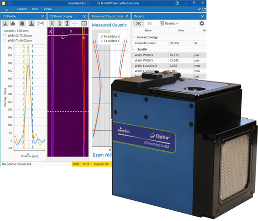
BeamWatch permits real-time measurements of the laser's M² (beam propagation ratio), K (1/M²), and BPP (beam parameter product). These measurements define the applicability of the laser for the task at hand.
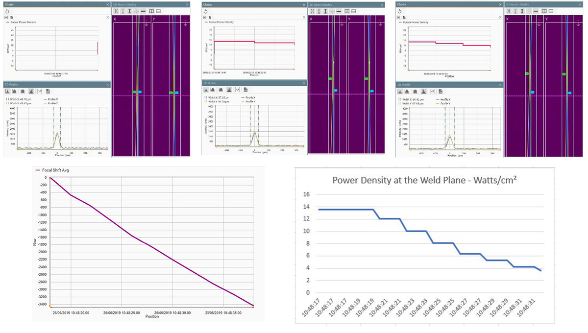
As shown in Figure 2, three screen captures of the BeamWatch application indicate progressive changes in the power density of the beam delivered to the weld plane. As the focal plane shifts toward the delivery optics, the power density at the weld plane decreases from 13.5MW/cm² to less than 4MW/cm². This change in the laser irradiance presented to the powder would cause catastrophic quality issues at this portion of the build.
Camera-based Beam Profiling
Camera-based beam profiling systems are coupled with a power meter to provide real-time beam profile measurements that are "calibrated" with the power measurement to create a power density map of the working spot that is delivered to the work plane.
Spatial resolution of scientific-grade CCD and CMOS camera sensors is finite and forms the lower limit of measurable spot sizes. A minimum of 10 pixels are needed to obtain meaningful beam width measurements.⁴
Beam profiling camera systems typically offer pixel pitches from 3.75μm to 10μm. The active area of a beam profile sensor should be a minimum of ~2-3 times of the 1/e² width of the beam being measured. Currently, available sensors offer active areas from 6.5 x 5mm to over 24 x 24mm².
Be careful to use the correct beam profile sensor for the laser wavelength. Silicon sensor based cameras operate in the 200 to 1100nm range. Due to the relative insensitivity of silicon in the near-IR, some camera sensors may not be appropriate for the longer wavelengths of 1070 – 1080nm fiber lasers. Some 2D, image sensors can distort the measured laser beam. Blooming and smearing are some of the more common sources of NIR laser beam measurement distortions.
When power densities are in excess of 1MW/cm², great care must be taken to obtain accurate measurements of the working laser beam. Dirty or damaged optics can severely distort the beam profile and may also cause errors in the power/energy measurement. High-power laser sensors are expected to survive power densities of 10kW/cm² without damage, so it is important to keep the optical surface of these sensors as clean as possible. Dirt and debris can reduce the lifetime and accuracy of these products. A blast of forced air or a careful cleaning with distilled water may occasionally be required. Always follow the manufacturer's directions.
Combining Power Measurements with Beam Profiles
Combining the total integrated power measurement of the laser beam with a time-relevant beam profile measurement enables the acquisition of power density maps for successful builds that can be archived and compared to subsequent profiles. Most beam profiling systems provide capabilities to establish pass / fail windows for all the laser performance parameters critical to successful builds. By measuring the powder and obtaining a power density map of the beam that is interacting with the powder, an informed assessment of the goodness of the process can be made. Any variations from historic performance can be compared to known additive manufacturing norms.
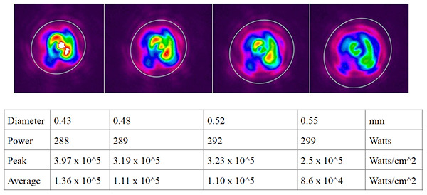
By combining beam profile images with measurements of the total power delivered to the powder bed, a complete representation of the energy density profile of the laser beam can be understood. With a series of beam profiles taken every 20ms, beginning with a cold start, the effects of thermal equalization of the beam delivery optics can be observed.
As you can see in Figure 4, as the delivery system heats up the beam, it is spread slightly. The consequences of this slight enlargement of the beam can clearly be seen in the computed peak and average power within the beam.
Protective windows are used in most powder bed machines to provide a barrier between the build chamber and the laser and delivery optics. Condensation from the outgassing collects on these windows and over time partially obscures the delivered beam leading to lower power and a broadening of the delivered focused spot. Both of these changes reduce the amount of energy that is available to the process. This can lead to incompletely formed structures with inconsistent mechanical properties.
Conclusion
Hybrid systems that employ multiple sensors provide meaningful insight into laser-powered AM processes. Laser power/energy data combined with the laser beam dimensions and profile provide an unparalleled level of understanding of the metal powder bed fusion processes. Intensity-calibrated beam profiles of the laser beam at the working plane help establish process norms. Pass/fail tests can alert AM systems operators when laser parameters fall outside of the established performance standards.
References
1. Optical Fiber Power Meter Calibrations at NIST, NIST Special Publication 250-54, Igor Vayshenker Xiaoyu Li David J. Livigni Thomas R. Scott Christopher L. Cromer
2. Processing parameters in laser powder bed fusion metal additive manufacturing, J.P. Oliveira, A.D. LaLonde, J. Ma
3. Characterizing the effects of laser control in laser powder bed fusion on near-surface pore formation via combined analysis of in-situ melt pool monitoring and X-ray computed tomography, F.H. Kim, H. Yeung, E.J. Garboczi
4. Beam width measurement accuracy. https://www.ophiropt.com/laser--measurement/knowledge-center/article/8117
5. BeamGage® camera based laser beam profilers. https://www.ophiropt.com/laser--measurement/beam-profilers/products/Beam-Profiling/Camera-Profiling-with-BeamGage