Measuring Challenges of Wide and Divergent Beams
VCSELs, LEDs, edge emitting, and fiber lasers are used in many sensitive applications within fast-growing markets. To guarantee the high quality of the devices, it is essential to analyze the beam profile, but those wide, divergent beams place specific requirements on the measurement system. On the one hand, the apertures of conventional beam profilers are too small to collect the entire spot of large or divergent light sources. On the other hand, diverging beams cannot be accurately measured with regular detectors because the quantum efficiency of the detector is highly dependent on the angle of incidence. These challenges have now been addressed with the development of the Ophir Wide Beam Imager – WB-I, a calibrated optical accessory for beam profiling cameras, based on diffuser with 45mm diameter aperture and a imaging lens that is designated for far field measurement.
Author:
Yoni Groisman, Karol Sanilevitch, Roei Yiftah, Dr. Simon Rankel
Applications and Limitations
There are several types of wide or divergent light sources, such as LEDs or fiber optic illuminators, that can be measured with the Wide Beam Imager, but its main application is the far field measurement of VCSELs. Vertical Cavity Surface Emitting Lasers (VCSELs) are a type of semiconductor laser diode. Unlike edge emitting laser diodes, VCSELs emit upwards and thus can be easily packaged as emitter arrays containing hundreds of emitters on a single chip.
Low power VCSELs are used for high speed data communication, 3D sensing (like gesture and facial recognition), and proximity sensors, while high power VCSELs are designated for LIDARs and other remote sensing applications. Many of these applications run on batteries, thus power consumption needs to be minimized. To ensure the proper operation of the VCSEL devices, it is essential to measure and analyze VCSEL power, beam profile, and noise. While there are many methods for measuring the radiant power of VCSELs, profiling their output beam usually requires bulky laboratory equipment that does not fit into production lines and is inconvenient for "in situ" tests.
The second challenge revolves around the angle of incidence: The quantum efficiency of standard detectors (such as silicon-based photodiodes or CCD sensors) highly depends on the angle of incidence - by as much as 10 % for every 15-degrees. Thus, they cannot accurately measure diverging beams. WB-I captures the beam and images its power distribution onto the camera with an accuracy of better than 5%. Let's look at how that precision be achieved.
Imaging a Wide Beam
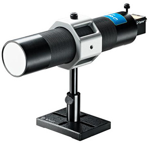
The WB-I device captures wide beams on a diffusive screen and re-images them to produce a complete and accurate mapping of the light's intensity distribution. The compact optical system is designed for use with camera-based beam profiling systems together with the Ophir BeamGage measurement software. WB-I is a ruggedized, compact, dust-proof, "ready to use" accessory intended for both production environments and service at a customer site. With its 45 mm diameter aperture and an angle of incidence of 140 degrees, beams of any beam shape (round, line, or square) that are too divergent and too large for a camera sensor can be imaged (Fig 2) by a defined scaling factor. The measurement itself is instant and requires minimal settings to be optimized for various illumination intensities. The distance between the light source being measured and the WB-I diffuser varies between single mm to a few tens of mm, depending on test type and application.
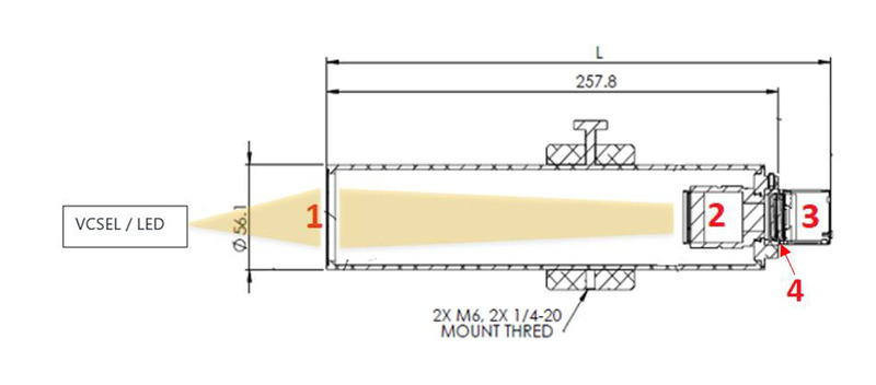
Components of the WB-I (Fig. 2):
- Opaque diffusive surface (1) with 45mm CA
- Imaging lens (2)
- Camera (3), e.g. Ophir SP920s, with BeamGage software (separately available)
- Two ND filters (4)
Let's have a closer look for what and how to use the WB-I.
VCSEL Beam Profiling
As discussed, the VCSEL energy distribution directly depends on parameters such as current, pulse width and repetition rate, temperature, and life of the device. Therefore, it is essential to measure the angle distribution of VCSELs at various stages of the manufacturing process as well as in R&D and field service. The WB-I accessory enables the flexible measurement of divergent beams and delivers valuable insights in different scenarios:
VCSEL behavior on the LIV sweep test
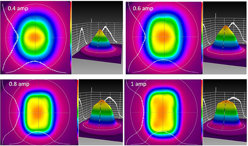
VCSELs are in a so called "LED mode" when there is only a low current applied. Once the current applied to the VCSEL rises, its beam profile changes to "Laser mode." This shift happens very rapidly and detecting exact electrooptical values during this process is highly important. This is one reason why the "Light-current-voltage (LIV) sweep test" is used to characterize a laser diode in operation. Observing beam profile changes during such a test provides important additional information. As the WB-I accessory, together with the camera and the BeamGage software, provides real time beam shape analysis and visualization, changes of the beam shape due to different applied currents can be easily detected.
VCSEL without diffuser cover
Depending on the application and the production stage, VCSELs can be measured with their diffuser cover or without it. In both cases, measurement can be performed using the WB-I device. Following are two examples of VCSEL arrays with and without a diffuser cover.
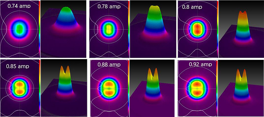
As the changes in beam shape can be tracked as a function of the applied current, any electronic or optic deviations of the product can be easily diagnosed.
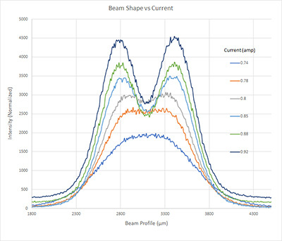
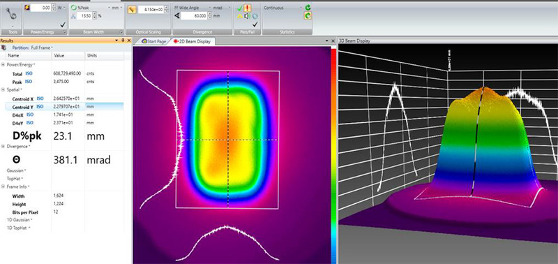
Figure 4 is a graph of the beam shape change vs current. It clearly shows that the Gaussian beam becomes flat top and shifts to dual mode once the current changes from 0.74 A to 0.92 A.
VCSEL with diffuser cover
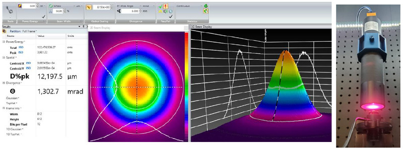
Below is an example of the beam profile of another VCSEL array sample with diffuser that shows different angular energy distribution.
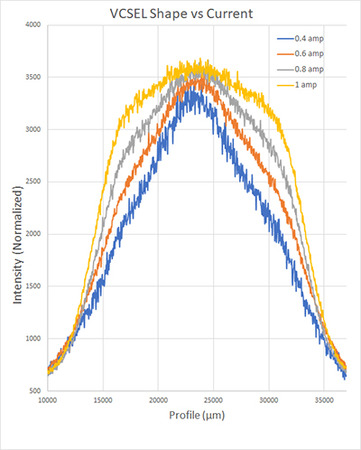
The cross section of the beam profile of the sample VCSEL with diffuser cover (see fig 6) illustrates the shift of the shape from gaussian to square-like. Top hat and total power increase with applied current.
Beam Divergence Measurement
In order to measure the beam divergence – which is important for judging the quality of VCSELs, LEDs, and fiber illumination devices - accurate measurement of angular illumination is essential.
The opaque diffuser used in the WB-I allows measurement of divergent beams up to 140° AOI, much better than other techniques such as knife edge, based on the usage of a power meter. Figure 7 demonstrates the differences between the measurements of a photodiode sensor vs. a WB-I with camera. With increasing angles, the power readings of the photodiodes are no longer reliable.
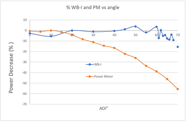
Due to the uniform diffusion of light at wide incidence angles, WB-I allows for measurement of very divergent beams, up to 70 deg° AOI (140 deg° opening angle)
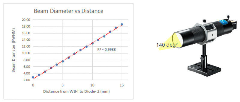
As shown in fig. 8, analyzing the beam diameter as function of the distance between the source and WB-I delivers additional insights. In our example, it shows linear behavior over the entire range. This enables accurate measurement of the divergence angles of the light sources. In order to calculate the divergence, it is essential to enter the distance between the light source and the diffuser of the WB-I accessory into the BeamGage software. Based on that input and the measured beam width (or a pre-selection by the user), the algorithm calculates the divergence displayed in mrad or deg°.
Again, differences can appear when measuring VCSELs: They show different divergence for different currents as they shift from "LED mode" to "Laser mode."
Divergence measurement of LEDs with the WB-I
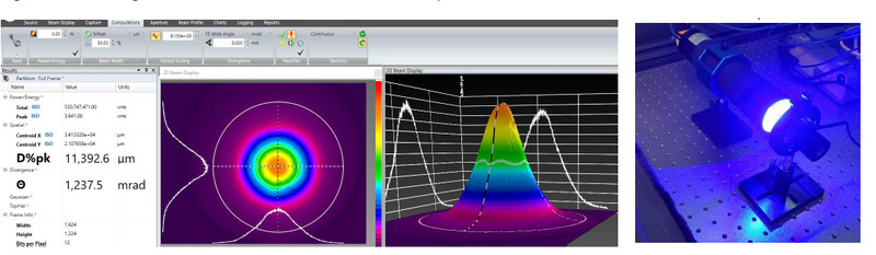
As mentioned, the WB-I not only measures VCSELs but also LEDs. As their divergence is generally much higher than that of VCSELs, tests have been performed with two different LED sources. Results can be seen in figures 10 and 11.
Divergence calculation – Tips and tricks
In order to obtain reliable measurements, especially with very divergent beams, there are some software related tips we want to share:
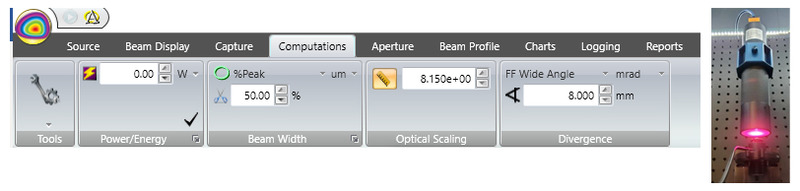
- In BeamGage computation tab, we recommend using Beam Width calculation of FWHM – 50% Peak.
- "Optical Scaling" parameter should be 8.15, fitting to CCTV lens of WB-I.
- Divergence calculation should be per "FF Wide angle" (Far Field) and distance of WB-I diffuser to light source should be inserted. * In case of very diverging light sources, like LEDs, we recommend locating it close to WB-I diffuser. Above 8mm, the divergence calculation may show incorrect results. For less diverging light sources, such as lasers or VCSELs, the distance for divergence calculation could be up to tens of mm's.
WB-I measurement of light sources showing a speckle pattern Speckle challenges
When measuring collimated laser beams, an interaction between laser and diffusive structure of WB-I surface may cause speckle pattern on the beam profiler sensor. This phenomenon is caused by the interference of monochromatic laser light and scattering surface. It can easily be smoothened with a software algorithm of the BeamGage software.
By using the Low Pass Filter (LPF) function in the BeamGage software the observed speckle can be significantly reduced as it turns a beam profile with a lot of spatial noise into an optimized image.
To learn more about data smoothing convolution algorithm, see this presentation.
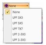
BeamGage software LPF function is located in the "Capture" tab > and can be found in the "Processing" panel:
Application example using the LPF function
In the below described situation the diverging beam of 632 nm HeNe laser was measured with the WB-I system. Severe speckle pattern was observed. Different low pass filters were used to smooth the speckle effect.
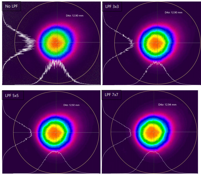
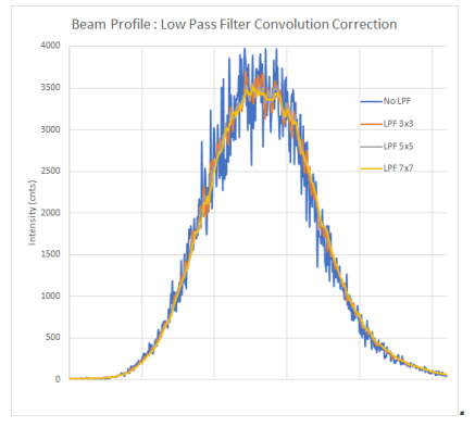
As demonstrated, the LPF function smoothed the speckle effect without compromising beam width (D4σ), intensity and other beam parameters.
Additionally, please note this application tip:
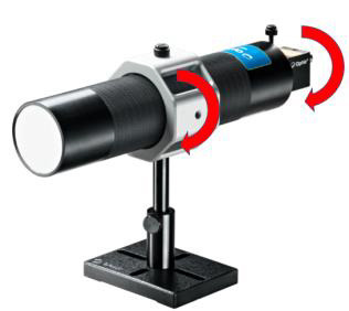
The WB-I setup can be positioned both horizontally and vertically. This way both the camera and the entire setup can be easily rotated to fit any light source orientation.
Conclusion
By developing the WB-I accessory, Ophir simplified the measurement of widely divergent light sources. VCSELs and LEDs can now be easily measured within the production process, in R&D, and at customer sites. The combination of the WB-I instrument with a beam profiler camera and the BeamGage software quickly delivers reliable measurement results. Far-field beam profiling of diverging or wide sources no longer requires extensive preparation or individually built equipment but can be performed with a calibrated measurement device.