Camera Based Beam Profiling with BeamGage
See your beam as never before with BeamGage®. The camera-based beam profiling system consists of a camera and analysis software. Often times, this system will need to be used with beam attenuation or beam sizing accessories, depending on your laser application. The advantage to camera-based beam profiling is the real-time viewing and measuring of a laser’s structure. BeamGage software includes an extensive set of ISO quantitative measurements, features a rich graphical interface, and features its patented UltraCal™ algorithm, providing the industry’s highest accuracy measurements.
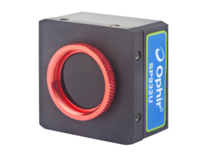
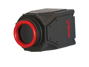
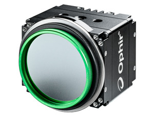
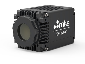
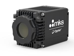
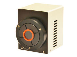
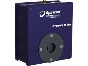
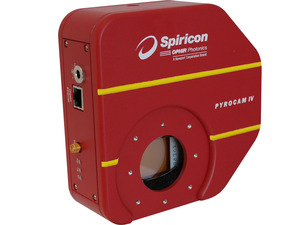
Cameras
|
BeamGage® Standard
Software comparison chart | BeamGage® Standard |
Features Overview | User selectable for either best "accuracy" or "ease of use" |
Supports our patented Ultracal algorithm plus Auto-setup and Auto-exposure capabilities | |
Extensive set of ISO quantitative measurements | |
Support for USB, GigE and Pyrocam™ IIIHR and Pyrocam™ IV cameras | |
New Beam Maker® beam simulator for algorithm self validation. See below for more detailed description. | |
Simultaneous 2D and 3D displays | |
Multi-instance, multi-camera use | |
Results synchronized to select models of Ophir power/ energy meters. Supported products include: Vega, Nova II, Pulsar, USBI and Juno, in both 32 and 64bit OS. (Quasar is not supported) | |
Supports Satellite windows on multiple monitors | |
Continuous zoom scaling in both 2D and 3D | |
Camera ROI support on USB and GigE cameras | |
Manual and Auto-aperturing to reduce background effects | |
Pass/Fail on all results items, w/multiple alarm options | |
Beam Pointing Stability scatter plot and stripchart results | |
Full featured logging capabilities in a reloadable Industry standard data file format | |
Configurable Report Generator that allows cut and paste of results, images and settings. | |
Supports English, German, Japanese and Chinese (Windows 7) and Windows 10 | |
Multilingual GUI in English, Japanese and Chinese. | |
Administrator can lock software options for nonadministrators | |
Quantitative Calculations; Basic Results | (per ISO 11145, 11146-1/-3, and 13694) |
Power/Energy Results | Total power or energy (Can be calibrated or sync'd to an external power/energy meter) |
Peak power/energy density | |
Min. Fluence | |
Average pulse power | |
Peak pulse power | |
Device efficiency | |
% in Aperture | |
Spatial Results | Peak and Centroid locations |
Beam width | |
![]() | |
![]() | |
![]() | |
![]() | |
![]() | |
![]() | |
![]() | |
Beam diameter | |
![]() | |
![]() | |
![]() | |
![]() | |
Elliptical Results | |
![]() | |
![]() | |
![]() | |
Distance Measurement | |
![]() | |
![]() | |
Area Results | |
Beam cross-sectional area | |
Divergence | Focal Length method |
Far-field two-point method | |
Far-field Wide Angle method | |
Gaussian Fit | 2D whole beam fits |
1D line fits | |
Height | |
Width X/Y | |
Centroid | |
Goodness of fit | |
Roughness of fit | |
Tophat Results | 2D and 1D |
Flatness | |
Effective Area | |
Effective Power/Energy | |
Fractional Effective Power/Energy | |
Effective Average Fluence | |
Uniformity | |
Plateau Uniformity | |
Edge Steepness | |
1D or 2D surface inclination | |
Other Quantitative Items | Frame Averaging |
Frame Summing | |
Frame Reference Subtraction | |
Image Convolution | |
Camera signal/noise calculator | |
Row and Column summing with results loggable | |
Beam Stability Displays and Results | (per ISO 11670) |
Pointing Stability of Centroid | |
![]() | |
![]() | |
![]() | |
![]() | |
![]() | |
![]() | |
![]() | |
![]() | |
![]() | |
![]() | |
![]() | |
![]() | |
![]() | |
![]() | |
![]() | |
![]() | |
![]() | |
![]() | |
![]() | |
![]() | |
![]() | |
Custom Calculations | |
Beam Profile Display Options | Utilizes advanced hardware accelerated graphics engines. All display windows can be satellited to utilize multiple display monitors. |
Can open one each simultaneous 2D and 3D beam display windows | |
Common color palette for 2D and 3D displays | |
Can open X and/or Y 1D beam slice profiles overlaid onto the 2D or 3D displays or in separate windows | |
Continuous software zooming in both 1D, 2D and 3D displays | |
Pan to any detector location | |
Continuous Z axis display magnitude scaling | |
Multiple 128 color palettes user selectable | |
Results items can be pasted into 2D, 3D, 1D, Pointing stability or Chart display windows. | |
1D Features | Available overlaid with 2D and 3D or in separate windows |
X and Y plots on separate or combined displays | |
1D displays with basic results and column row summing option | |
Tophat 1D displays with Tophat results | |
Gaussian 1D displays with Gaussian fit results | |
1D Profile display of the Gauss fit results on 1D, 2D and 3D displays | |
2D Features | Continuously zoomable and resizable displays in floatable window |
Continuous Z axis display magnitude scaling | |
Zoomable to subpixel resolution for origin and cursor placements | |
Pixel boundaries delineated at higher zoom magnifications | |
Adjustable Cursors that can track peak or centroid | |
Adjustable Crosshairs that can track peak or centroid | |
Adjustable manual apertures | |
Viewable Auto-aperture placement | |
Displayed beam width marker | |
Integrated Mouse actuated pan/zoom controls | |
Separate 2D pan/zoom window to show current view in 2D beam display | |
Manual or fixed origin placement | |
3D Features | 3D graphics utilize solid surface construction with lighting and shading effects |
Integrated Mouse actuated pan/zoom/tilt/rotate controls | |
Selectable Mesh for drawing speed vs resolution control | |
Continuously zoomable and resizable displays in floatable window | |
Continuous Z axis display magnitude scaling | |
User enabled backplanes with cursor projections | |
Statistical Analysis | Performed on all measurement functions with on-screen display |
![]() | |
![]() | |
![]() | |
![]() | |
Measurements reported | |
![]() | |
Controls integrated with beam stability results, scatter and strip chart plots | |
File types | Industry Standard HDF5 data and setup file format which are compatible in third party applications such as MatLab and Mathmatica |
Math program and Excel compatable csv results files | |
Graphics in jpg file format | |
Legacy file Compatibility with LBA formats | |
A user defined single file output that can contain settings, beam displays, beam profiles, charts, results, etc. in either .pdf or .xps file formats | |
Printing | Images, reports, results, graphs, charts, statistics and setup information |
Option to print many frames in a single operation | |
WYSIWYG images | |
Pass/Fail | Set Maximum/Minimum limits on all calculations and statistics |
Red/Green font color indication on result items | |
Multiple choices for indication of failed parameters, including TTL pulse for external alarm | |
Master pass/fail which triggers alarm on any failure | |
USB/GigE signal, beep, stop, and log alarm options | |
Logging | Video Data Logging Formats: HDF5, ASCII-csv |
Results in ASCII-csv | |
Pictures 2D and 3D in jpg, gif, tiff, bmp, png file formats | |
Charts in ASCII-csv | |
Cursor Data in ASCII-csv | |
Row/Column summed in ASCII-csv | |
Continuous Logging | |
Time Interval Logging | |
Frame Count Logging | |
Periodic Sampling | |
Pass/Fail Sampling | |
Burst Sampling, after a user specified time interval, sample a user specified number of frames | |
Exporting | Convert frame buffer data to third party format |
Export a user specified number of frames from the buffer | |
Export Image Data: ASCII-cvs | |
Export Results: ASCII-csv | |
Export Picture: jpg, gif, tiff, bmp, png file formats supported | |
Export Cursor Data: ASCII-cvs | |
Export Row/Column summed: ASCII-cvs | |
Export Image Data in Aperature | |
Integrated Help | PDF Operators Manual |
Context Sensitive Help | |
Context Sensitive Hints | |
Signal Conditioning for Enhanced Accuracy | Spiricon’s patented Ultracal enables more accurate beam measurement and display. Ultracal takes a multi- frame average of the baseline offset of each individual pixel to obtain a baseline accurate to approximately 1/8 of a digital count. This baseline offset is subtracted from each frame, pixel by pixel, to obtain a baseline correction accurate to 1/8 digital count. Spiricon’s Ultracal method retains numbers |
less than zero that result from noise when the baseline is subtracted. Retaining fractional and negative numbers in the processed signal can increase the beam width measurement accuracy by up to 10X over conventional baseline subtraction and clip level methods. Spiricon's Ultracal conforms to the best method described in ISO 11146-3:2004 | |
Frame Averaging | Up to 256 frames can be averaged for a signal-to-noise ratio, S/N, improvement of up to 16X (Noise is averaged up to 1/256th [8 fractional bits]). Data is processed and stored in a 32bit format. |
Frame Summing | Up to 256 frames can be summed to pull very weak signals out of the noise. |
Due to the precise nature of Ultracal baseline setting, (i.e., a retention of both positive and negative noise components) summing of frames can be performed without generating a large offset in the baseline. | |
Convolution (Adjacent Pixel Averaging) | Choice of 5 convolution algorithms for spatial filtering for both display and calculations. Spatial filtering improves the visual S/N. |
Beam Maker® | Beam Maker is a new feature that allows the user to model both Laguerre-Gaussian and Hermite-Gaussian laser beams in various modal configurations. With these models you have verification and validation tools that allows not only OSI but also the end user to verify BeamGage’s basic beam width measurement algorithms. It can also be used to model laser beams with special input conditions such as signal-to-noise, background offset, and bits per pixel resolution. This allows the user to better understand the accuracy of measurements made under both optimum and adverse conditions. This tool provides the user with a method to validate algorithms against current ISO standards and methods. It can also be used to validate third party algorithms by making the output data available for use in third party applications. |
Camera Features | Camera features are governed by the capabilities of the various cameras that will interfaced with these software products, and second by which of these camera features are implemented in the software. This section will describe typical camera features supported in the application. |
Black Level Control (used by Ultracal and Auto-X and Auto-setup) | |
Gain Control (used by Auto-X and Auto-setup) | |
Exposure Control (used by Auto-X and Auto-setup) | |
User Programmable ROI | |
Pixel Binning | |
Pixel Sampling | |
Bits per pixel setting | |
External Trigger Input | |
Trigger Delay | |
Strobe Output | |
Strobe Delay | |
External Trigger Probe | |
Internal Trigger Probe | |
Camera related features in the applications | These are features related to but not generally dependant upon the camera design. |
Gamma Correction | |
Gain Correction | |
Bad Pixel Correction | |
Lens Applied Option | |
Pixel scale settings | |
Magnification settings | |
Frame buffer settings | |
Ultracal | |
Enable Auto-X (auto exposure control) | |
Perform an Auto-Setup | |
8/10/12/14/16 bits per pixel | |
Select Format or ROI | |
Measure S/N ratio | |
Trigger, Capture and Synchronization Methods | Capture methods are features related to the application while Synchronization methods relate more to the abilities of the specific camera. NOTE: Frame capture rates are determined by many factors and are not guarenteed for any specific operating configuration. |
Trigger modes | |
![]() | |
![]() | |
![]() | |
![]() | |
Capture options | |
![]() | |
![]() | |
![]() | |
![]() | |
![]() | |
![]() | |
Post processing is still available but is done via a different mechanism and is limited to only data file sources. | |
Video Playback | Video playback, post processing and post analysis |
User customizable playback rates | |
Video file quick pan/search controls | |
Whole video file playback looping with sub-selection looping | |
Playback Video produced by logging | |
Almost all measurements can be performed on video files | |
System Requirements | PC computer running Windows 7 (64) and Windows 10 Laptop or Desktop |
Not all cameras run in all Microsoft OS versions, see camera section for specifics | |
GHz Pentium style processor, dual core recommended | |
Minimum 2GB RAM (4GB required for L11059 camera) | |
Accelerated Graphics Processor | |
Hard drive space suitable to hold the amount of video data you expect to store (50-100 GB recommended) |
BeamGage® Professional
All Features in Standard Plus Those highlighted in Yellow
Software comparison chart | BeamGage® Professional |
Features Overview | User selectable for either best "accuracy" or "ease of use" |
Supports our patented Ultracal algorithm plus Auto-setup and Auto-exposure capabilities | |
Extensive set of ISO quantitative measurements | |
Supports InGaAs and large format L11059 cameras | |
New Beam MakerTM beam simulator for algorithm self validation. See below for more detailed description. | |
Simultaneous 2D and 3D displays | |
Multi-instance multi-camera use | |
Results synchronized to select models of Ophir power/ energy meters. Supported products include: Vega, Nova II, Pulsar, USBI and Juno, in both 32 and 64bit OS. (Quasar is not supported) | |
Supports Satellite windows on multple monitors | |
Continuous zoom scaling in both 2D and 3D | |
Window partitioning to allow analysis of multiple beams from a single camera image | |
Camera ROI support on USB and GigE cameras | |
Manual and Auto-aperturing to reduce background effects | |
Pass/Fail on all results items, w/multiple alarm options | |
Beam Pointing Stability scatter plot and stripchart results | |
Full featured logging capabilities that are reloadable Industry standard data file format | |
Configurable Report Generator that allows cut and paste of results, images and settings. | |
.NET Automation interface that allows for full remote control Examples in LabView, Excel and .Net VB | |
Supports English, German, Japanese and Chinese (Windows 7) and Windows 10 | |
Multilingual GUI in English, Japanese and Chinese. | |
Administrator can lock software options for nonadministrators | |
Quantitative Calculations; Basic Results | (per ISO 11145, 11146-1/-3, and 13694) |
Power/Energy Results | Total power or energy (Can be calibrated or sync'd to an external power/energy meter) |
Peak power/energy density | |
Min. Fluence | |
Average pulse power | |
Peak pulse power | |
Device efficiency | |
% in Aperture | |
Spatial Results | Peak and Centroid locations |
Beam width | |
![]() | |
![]() | |
![]() | |
![]() | |
![]() | |
![]() | |
![]() | |
Beam diameter | |
![]() | |
![]() | |
![]() | |
![]() | |
Elliptical Results | |
![]() | |
![]() | |
![]() | |
Distance Measurement | |
![]() | |
![]() | |
Area Results | |
Beam cross-sectional area | |
Divergence | Focal Length method |
Far-field two-point method | |
Far-field Wide Angle method | |
Gaussian Fit | 2D whole beam fits |
1D line fits | |
Height | |
Width X/Y | |
Centroid | |
Goodness of fit | |
Roughness of fit | |
Tophat Results | 2D and 1D |
Flatness | |
Effective Area | |
Effective Power/Energy | |
Fractional Effective Power/Energy | |
Effective Average Fluence | |
Uniformity | |
Plateau Uniformity | |
Edge Steepness | |
1D or 2D surface inclination | |
Other Quantitative Items | Frame Averaging |
Frame Summing | |
Frame Reference Subtraction | |
Image Convolution | |
Camera signal/noise calculator | |
Row and Column summing with results loggable | |
Scalable Intensity Histogram, exportable | |
X or Y axial off axis image correction | |
Beam Stability Displays and Results | (per ISO 11670) |
Pointing Stability of Centroid | |
![]() | |
![]() | |
![]() | |
![]() | |
![]() | |
![]() | |
![]() | |
![]() | |
![]() | |
![]() | |
![]() | |
![]() | |
![]() | |
![]() | |
![]() | |
![]() | |
![]() | |
![]() | |
![]() | |
![]() | |
![]() | |
![]() | |
Custom Calculations | User can program-in own set of calculations |
Beam Profile Display Options | Utilizes advanced hardware accelerated graphics engines. All display windows can be satellited to utilize multiple display monitors. |
Can open one each simultaneous 2D and 3D beam display windows | |
Common color palette for 2D and 3D displays | |
Can open X and/or Y 1D beam slice profiles overlaid onto the 2D or 3D displays or in separate windows | |
Continuous software zooming in both 1D, 2D and 3D displays | |
Pan to any detector location | |
Continuous Z axis display magnitude scaling | |
Multiple 128 color palettes user selectable | |
Results items can be pasted into 2D, 3D, 1D, Pointing stability or Chart display windows. | |
Able to partition the camera imager into multiple regions with separate results. | |
1D Features | Available overlaid with 2D and 3D or in separate windows |
X and Y plots on separate or combined displays | |
1D displays with basic results and column row summing option | |
Tophat 1D displays with Tophat results | |
Gaussian 1D displays with Gaussian fit results | |
1D Profile display of the Gauss fit results on 1D, 2D and 3D displays | |
2D Features | Continuously zoomable and resizable displays in floatable window |
Continuous Z axis display magnitude scaling | |
Zoomable to subpixel resolution for origin and cursor placements | |
Pixel boundaries delineated at higher zoom magnifications | |
Adjustable Cursors that can track peak or centroid | |
Adjustable Crosshairs that can track peak or centroid | |
Adjustable manual apertures | |
Viewable Auto-aperture placement | |
Displayed beam width marker | |
Integrated Mouse actuated pan/zoom controls | |
Separate 2D pan/zoom window to show current view in 2D beam display | |
Manual or fixed origin placement | |
Ability to create partitions using the manual aperture controls | |
3D Features | 3D graphics utilize solid surface construction with lighting and shading effects |
Integrated Mouse actuated pan/zoom/tilt/rotate controls | |
Selectable Mesh for drawing speed vs resolution control | |
Continuously zoomable and resizable displays in floatable window | |
Continuous Z axis display magnitude scaling | |
User enabled backplanes with cursor projections | |
Partitioning | Users can subdivide the imager into separate beam measurement regions. All enabled results are computed inside of each partition |
The manual aperture is used to define and create rectangular partition | |
When partitioning is enabled some new results items will be enabled | |
Centroid measurements between beams in each partition can be performed | |
Partitioned imagers must have a single origin common to all partitions. All coordinate results are globally referenced to this single origin | |
Statistical Analysis | Performed on all measurement functions with on-screen display |
![]() | |
![]() | |
![]() | |
![]() | |
Measurements reported | |
![]() | |
Controls integrated with beam stability results, scatter and strip chart plots | |
File types | Industry Standard HDF5 data and setup file format which are compatible in third party applications such as MatLab and Mathmatica |
Math program and Excel compatable csv results files | |
Graphics in jpg file format | |
Legacy file Compatibility with LBA formats | |
A user defined single file output that can contain settings, beam displays, beam profiles, charts, results, etc. in either .pdf or .xps file formats | |
Printing | Images, reports, results, graphs, charts, statistics and setup information |
Option to print many frames in a single operation | |
WYSIWYG images | |
Pass/Fail | Set Maximum/Minimum limits on all calculations and statistics |
Red/Green font color indication on result items | |
Multiple choices for indication of failed parameters, including TTL pulse for external alarm. | |
Master pass/fail which triggers alarm on any failure | |
USB/GigE signal, beep, stop, and log alarm options | |
Logging | Video Data Logging Formats: HDF5, ASCII-csv |
Results in ASCII-csv | |
Pictures 2D and 3D in jpg, gif, tiff, bmp, png file formats | |
Charts in ASCII-csv | |
Cursor Data in ASCII-csv | |
Row/Column summed in ASCII-csv | |
Continuous Logging | |
Time Interval Logging | |
Frame Count Logging | |
Periodic Sampling | |
Pass/Fail Sampling | |
Burst Sampling, after a user specified time interval, sample a user specified number of frames | |
Exporting | Convert frame buffer data to third party format |
Export a user specified number of frames from the buffer | |
Export Image Data: ASCII-cvs | |
Export Results: ASCII-csv | |
Export Picture: jpg, gif, tiff, bmp, png file formats supported | |
Export Cursor Data: ASCII-cvs | |
Export Row/Column summed: ASCII-cvs | |
Export Image Data in Aperature | |
Automation Interface (.NET) | Automation Interface with examples in LabVIEW, Excel and .Net VB |
Automate launch and termination of the application | |
Automate start, stop, Ultracal, Auto-X and Auto Setup | |
Automate the loading of application setups | |
Automate control of most camera settings | |
Automate a subset of the application features and controls | |
Automate the capture of Binary Video Data | |
Automate the acquisition of aplication results | |
Automate the acquisition of aplication Images | |
Integrated Help | PDF Operators Manual |
Context Sensitive Help | |
Context Sensitive Hints | |
Signal Conditioning for Enhanced Accuracy | Spiricon’s patented Ultracal enables more accurate beam measurement and display. Ultracal takes a multi- frame average of the baseline offset of each individual pixel to obtain a baseline accurate to approximately 1/8 of a digital count. This baseline offset is subtracted from each frame, pixel by pixel, to obtain a baseline correction accurate to 1/8 digital count. Spiricon’s Ultracal method retains numbers |
less than zero that result from noise when the baseline is subtracted. Retaining fractional and negative numbers in the processed signal can increase the beam width measurement accuracy by up to 10X over conventional baseline subtraction and clip level methods. Spiricon's Ultracal conforms to the best method described in ISO 11146-3:2004 | |
Frame Averaging | Up to 256 frames can be averaged for a signal-to-noise ratio, S/N, improvement of up to 16X (Noise is averaged up to 1/256th [8 fractional bits]). Data is processed and stored in a 32bit format. |
Frame Summing | Up to 256 frames can be summed to pull very weak signals out of the noise. |
Due to the precise nature of Ultracal baseline setting, (i.e., a retention of both positive and negative noise components) summing of frames can be performed without generating a large offset in the baseline. | |
Convolution (Adjacent Pixel Averaging) | Choice of 5 convolution algorithms for spatial filtering for both display and calculations. Spatial filtering improves the visual S/N. |
Beam Maker® | Beam Maker is a new feature that allows the user to model both Laguerre-Gaussian and Hermite-Gaussian laser beams in various modal configurations. With these models you have verification and validation tools that allows not only OSI but also the end user to verify BeamGage’s basic beam width measurement algorithms. It can also be used to model laser beams with special input conditions such as signal-to-noise, background offset, and bits per pixel resolution. This allows the user to better understand the accuracy of measurements made under both optimum and adverse conditions. This tool provides the user with a method to validate algorithms against current ISO standards and methods. It can also be used to validate third party algorithms by making the output data available for use in third party applications. |
Camera Features | Camera features are governed by the capabilities of the various cameras that will interfaced with these software products, and second by which of these camera features are implemente in the software. This section will describe typical camera features supported in the application. |
Black Level Control (used by Ultracal and Auto-X and Auto-setup) | |
Gain Control (used by Auto-X and Auto-setup) | |
Exposure Control (used by Auto-X and Auto-setup) | |
User Programmable ROI | |
Pixel Binning | |
Pixel Sampling | |
Bits per pixel setting | |
External Trigger Input | |
Trigger Delay | |
Strobe Output | |
Strobe Delay | |
External Trigger Probe | |
Internal Trigger Probe | |
Camera related features in the applications | These are features related to but not generally dependant upon the camera design. |
Gamma Correction | |
Gain Correction | |
Bad Pixel Correction | |
Lens Applied Option | |
Pixel scale settings | |
Magnification settings | |
Frame buffer settings | |
Ultracal | |
Enable Auto-X (auto exposure control) | |
Perform an Auto-Setup | |
8/10/12/14/16 bits per pixel | |
Select Format or ROI | |
Measure S/N ratio | |
Trigger, Capture and Synchronization Methods | Capture methods are features related to the application while Synchronization methods relate more to the abilities of the specific camera. NOTE: Frame capture rates are determined by many factors and are not guarenteed for any specific operating configuration. |
Trigger modes | |
![]() | |
![]() | |
![]() | |
![]() | |
Capture options | |
![]() | |
![]() | |
![]() | |
![]() | |
![]() | |
![]() | |
Post processing is still available but is done via a different mechanism and is limited to only data file sources. | |
Video Playback | Video playback, post processing and post analysis |
User customizable playback rates | |
Video file quick pan/search controls | |
Whole video file playback looping with sub-selection looping | |
Playback Video produced by logging | |
Almost all measurements can be performed on video files | |
System Requirements | PC computer running Windows 7 (64) and Windows 10 Laptop or Desktop |
Not all cameras run in all Microsoft OS versions, see camera section for specifics | |
GHz Pentium style processor, dual core recommended | |
Minimum 3-4GB RAM | |
Accelerated Graphics Processor | |
Hard drive space suitable to hold the amount of video data you expect to store. (50-100 GB recommended) |
Documentation
BeamGage Standard
BeamGage Standard is our full-function software with an extensive set of ISO quantitative measurement, our patented Ultracal™ algorithm for the highest accuracy measurements in the industry.BeamGage Professional
BeamGage Professional has all of the functionality that BeamGage Standard includes. BeamGage Professional supports all of our beam profiling cameras, includes window partitioning to allow analysis of multiple beams on a single camera, and includes an automation interface written in .NET to push data to your custom applications.
FAQ
How can I use BeamGage Professional with my BeamGage Standard camera system?
If your camera is licensed for Standard, you can add a higher level tier with a software upgrade that can be purchased for a fee. This includes the license code and the software DVD on a per camera basis. Instead of DVD, the BeamGage Professional software can be downloaded fromOphir site https://www.ophiropt.com/laser--measurement/software-download
BeamGage Professional allows you to run an automation interface and also allows partitioning of the array to take measurements of multiple beams.
CloseWhy does BeamGage have a Windows shield icon on the BeamGage desktop icon, or BeamGage asks me to log on as an Administrator to run the application?
In previous versions of BeamGage it was required to install and operate BeamGage with elevated privileges. The BeamGage 6.1 application core has been over hauled to eliminate the need for operating the software with elevated privileges. You still have to install BeamGage 6.1 from an Administrator level account, but now you can operate it OK with restricted user privileges.
CloseCan I use my beam profiling camera as a power meter?
A camera is not meant to be a power meter. Even though BeamGage has the ability to measure and display a power/energy reading, you first need to use a NIST calibrated power/energy meter to get a calibrated power or energy meter reading to relate it to a given beam profile that is taken simultaneously. Then you can have a relative power reading come from your BeamGage beam profiling camera system. In adition, BeamGage reading can indicate a trend of laser power at same settings. For example, if you have a laser source with known Power/Energy, you can mark that parameter in BeamGage>Computations>Power Energy tab, and see trend in case of increase or reduction in laser intensity.
If you use an Ophir USB based power/energy meter display you will be able to link this equipment into BeamGage to get a continual feedback from your Ophir equipment into BeamGage to create this connection for you. You need to keep your Ophir sensor in the beam path so it will continually update the related reading to the given beam profile.
CloseHow does BeamGage produce higher resolution pointing stability than the size of one pixel in the camera?
As BeamGage collects data points to put into the Pointing Stability function it allows you to see the concentration of where the data points are located. These are fitted to a distribution and you can get fractions of data that can produce information that is beyond the precision of the camera pixel.
An example would be if we collect 10 data points that have 5 points in one location and 5 points in a location just 1 pixel away. The distribution will indicate the centroid is in between these two points at 1/2 the pixel size. This is beyond the capability of the equipment, but the distribution mathematically is correct.
Close