仕様
- InGaAs
- <0.175 nsec
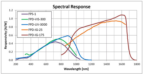
- 900-1700 nm
- 0.1 mm
- <0.03 pW/√Hz
- 54 L x 34 W x 40 D (mm)
- 0.0079 mm²
- 1600 nm
- 1.1 A/W
- 4.3 x 10⁻³ V/(W/cm²)
- 6 VDC
- Batteries
- >2 GHz
- <2 nA
- 10 mW
- 8-32 & M4
- BNC
- M20x1
- CE, UKCA, 中国RoHS
または弊社までお気軽にお問合せください。
カタログ&取説
FAQ
Do I need to recalibrate my instrument?
What kind of measurements can I do with a temporal detector? Why are they important?
With a temporal detector you can measure the rise time, fall time, pulse duration and pulse frequency. Many laser applications use pulsed laser, for example medical lasers, LIDARs, and high power fiber laser for metal processing to name a few. The parameters of the laser pulses are critical for the performance of the application.
閉じるThe temporal sensor can provide accurate measurement of temporal parameters. How can I relate those to absolute value of pulse energy?
Pulse energy can be measured directly using one of Ophir's calibrated energy sensors. Another way is to use a calibrated power sensor and calculate the pulse energy using:
Pulse energy [J] = average power [W] / pulse rate [pulses per second]
Temporal sensors provide a signal that is proportional to the instantaneous power output of the laser. When viewing the pulse waveform on an oscilloscope, the integrated area under the curve is proportional to the total pulse energy.
閉じるWhat is the difference between calibrated power sensors such as PD300 and temporal sensors?
Calibrated power sensorsmeasure the average power of CW and pulsed laser beams. The sensor is connected to an Ophir Meter or PC Interface. Power sensors are optimized for low noise and linear response in order to maximize power measurement accuracy. The measured laser beam must be smaller than the sensor's aperture in order to obtain an accurate power measurement. Temporal sensors are optimized for high speed response in order to reproduce pulse temporal characteristics with high fidelity. A temporal sensor is usually smaller than the laser beam size and samples a portion of the beam. The temporal sensor is connected to a scope or spectrum analyzer to display temporal characteristics of pulsed lasers.
閉じるI need to measure the temporal pulse shape of a very powerful laser. How can I do that without damaging the detector?
There are several possible ways to do this:
- Use a beam sampling optic (partially reflective mirror or uncoated window).
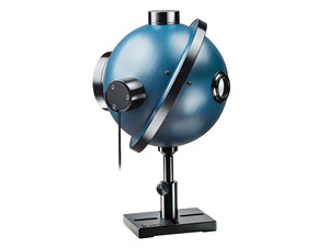
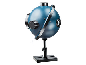
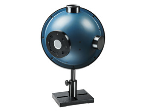
- Feed the laser beam into an integrating sphere and attach the temporal detector to the sphere using the adapter accessory.
- Use a beam dump and position the detector such that it picks up some of the reflected laser radiation.
Attenuating accessories are available (see temporal detector's product page). Laser power density on the attenuators should be less than 50 W/cm².
閉じるI don’t see my signal on the oscilloscope or the signal is not as expected. What should I do?
サーマルセンサでレーザパワーを測定しながら、オシロスコープでレーザの波形を測るにはどうしたらよいですか?
目的によって複数の選択肢があります。
- ディスプレイの内部演算処理による遅れ時間が問題にならない多くの場合、最も簡単な解決策はパワーメータのアナログ出力を利用することです。実際の読み値に比例する電圧信号(指示値をデジタル-アナログ変換してアナログ量に還元)を利用しますので、校正された読み値として出力されます。フルスケールの値は、接続しているパワーメータディスプレイと使用しているパワーレンジの関係により自動的に決定されます。
- オプションのSH-BNC変換コネクタ(製品番号P/N 7Z11010)を使用すれば、センサからの無加工の電気量をオシロスコープで波形観測できます。センサのコネクタ部分に組み込まれているEEROMには校正データの情報が記憶されており、オフィールのディスプレイやインターフェイスユニットではそれを基にして電気的に増幅し指示値に変換しているので、校正係数に全く依存しない純粋なアナログセンサとして単独動作させるためにSH-BNC変換コネクタを使用します。 注意点としては、レーザ出力がセンサの最大許容パワーに対して低すぎるとオシロスコープのノイズレベル程度の小さな信号にしかならず、この方法は入射光量に比例した信号としては取り出せないので必ずしも適切ではありません。
- 最低限の要求仕様を満たしていれば、FPS-1高速フォトディテクタをオシロスコープに接続してレーザのパルス波形そのものを実時間計測できます。ディテクタに反射光などの微弱光の一部を入射させ、光の強度の時間的変化を簡単にオシロスコープで波形確認することが可能です。
Calibration
Ophir's temporal sensors do not require calibration.
仕様
- InGaAs
- <0.175 nsec
- 900-1700 nm
- 0.1 mm
- <0.03 pW/√Hz
- 54 L x 34 W x 40 D (mm)
- 0.0079 mm²
- 1600 nm
- 1.1 A/W
- 4.3 x 10⁻³ V/(W/cm²)
- 6 VDC
- Batteries
- >2 GHz
- <2 nA
- 10 mW
- 8-32 & M4
- BNC
- M20x1
- CE, UKCA, 中国RoHS
アクセサリ
-
ND1 アッテネータ
7Z082001/10(代表値)
-
ND2 アッテネータ
7Z082011/50(代表値)
-
FPD~IS6アダプター
7Z08350FPDセンサー (FPS-1を除く) をIS6シリーズのノースポールにマウント
-
FC Fiber Adapter
7Z08229This fiber adapter is used for connecting power and energy sensors to a standard FC-type fiber. Many sensors need an additional mounting bracket to connect to all fiber adapters. More information can be found in the datasheet below. -
ST Fiber Adapter
7Z08226This fiber adapter is used for connecting power and energy sensors to a standard ST-type fiber. Many sensors need an additional mounting bracket to connect to all fiber adapters. More information can be found in the datasheet below. -
SC Fiber Adapter
7Z08227This fiber adapter is used for connecting power and energy sensors to a standard SC-type fiber. Many sensors need an additional mounting bracket to connect to all fiber adapters. More information can be found in the datasheet below. -
SMA Fiber Adapter
1G01236AThis fiber adapter is used for connecting power and energy sensors to a standard SMA-type fiber. Many sensors need an additional mounting bracket to connect to all fiber adapters. More information can be found in the datasheet below.