Power Meters FAQ's

Thermal Laser Power Sensors

Choosing a Sensor

05/25/15

Surface Absorbers are spectrally broadband and spectrally flat due to their absorbing surface. With Surface Absorbers, the photons are converted to heat in the front layer of the absorbing surface. The P and PF versions of these sensors have a surface that absorbs within the volume of the coating. This provides superior damage resistance for high energy Q-switched type lasers, but has a lower damage threshold for CW lasers. This type of sensor is referred to as a Volume Absorber; the laser energy is absorbed in the volume of the material below the front surface. For a detailed discussion of thermal surface and volume absorbing sensors and absorbers for high power lasers, click here.

04/11/19

The spectral range stated at the beginning of the spec indicates the range of wavelengths for which the sensor can be usefully used even if the exact calibration is not specified for that range. This means that over the calibrated wavelength range, the accuracy is specified and guaranteed. Over a wider useful wavelength range, the sensor is usable but no accuracy is guaranteed. In general over this wider range, the accuracy will be within up to ±15%.

05/14/23

Every case is unique, of course, and the reason for the Service Team to decide to replace the disc in one case might not be the same as their reason for so deciding in another case.

In general, though, what it comes down to is that if a given disc has a level of damage (or contamination that cannot be cleaned) such that the sensor will no longer be able to reliably measure with the specified accuracy, that would be a reason to replace the disc.

It should be noted that not every “marking” on a disc caused by laser exposure is necessarily “damage”. Sometimes it might be merely cosmetic. We generally define “damage” as a marking that changes the reading by 1% or more. If a given beam incident ON the marking reads more than 1% differently than the same beam NEXT TO the marking, then we consider that marking as damage.

In some cases, if there is a damage marking but it is small, perhaps near the outer edge of the aperture of the sensor where most of the time the beam will not actually be incident on it, a very experienced customer (perhaps an R&D physics team for example) might simply tell us to leave it as is, without repairing it, and they understand that they should avoid measuring on that one spot. For a sensor used in a Production environment, on the other hand, that would of course not be an option.

Again, every case is different, but hopefully the general idea is clear.

At the end of the day, we have to make sure we are providing our customers with a measurement instrument that will measure with the very highest possible accuracy.


Damage

06/09/14

We publish a nominal damage threshold for most of our thermal BB sensors as 20KW/cm2. Other manufacturers may quote higher numbers than this. In actuality, in one to one tests against competitors, our sensors show a higher damage threshold but the actual damage threshold depends on the total power as well as the power density. For very low powers such as 30W, the damage threshold can be as high as 50KW/cm2 and at high powers such as 5KW, it drops to 3KW/cm2. The Ophir sensor finder program takes account of these variations in its calculations.

05/26/15

The damage threshold curve in the sensors catalog only goes down to 1ns but the energy damage threshold is similar for shorter pulses. You can use ½ of the ns value for fs pulses i.e. the absorber damages twice as easily.

05/26/15

Corrosion is caused by interactions between the metallic components of the sensor and the cooling water, which may contain a variety of dissolved ions. Many factors affect the risk of corrosion forming, but the most important are the pH and the mixture of ions in the water. For this reason, we recommend using neutral deionized water in a closed circulating system (pH between 6 and 8). Please note that deionized water is usually slightly acidic (pH 5.65) due to absorption of CO2 from the atmosphere. The cooling water can be neutralized by adding 5 ml of a 10 mM solution of NaOH for each liter of water in the cooling system.
 
To prevent corrosion it is also crucial to not allow standing water to evaporate inside the sensor when it is not in use. When disconnecting a sensor from the cooling system, the water channel should be cleared by blowing compressed air through it.
 
The commercial additive Optishield Plus is also recommended for systems such as ours that have copper and aluminum in them. It has the additional benefit of having biocides to prevent buildup of organic contamination.
 
For those customers still experiencing problems with corrosion, we recommend the new thermal sensor 1000WP-BB-34 which has a special design in which all materials that come into contact with the cooling water are either copper or nonmetallic.

06/03/15

The damage threshold of thermal sensors does depend on the power level and not only the power density because the sensor disc itself gets hotter at high powers. For instance, the damage threshold of the Ophir broadband coating may be 50KW/cm2 at 10 Watts but only 10KW/cm2 at 300W. The Ophir specifications for damage threshold are always given for the highest power of use of a particular sensor, something which is not done by most other manufacturers. This should be taken into account when comparing specifications. The Sensor Finder takes the power level into consideration when calculating damage threshold.

 Watch the 'FAQ: Does damage threshold depend on power level?' video

11/07/16

Whether RS232 or Profinet is used, there is a command to query the current temperature. The customer is responsible for integrating this into the measurement script and coordinating with the laser control to make sure the laser is not allowed to be measured when the temperature is over the limit. If using the PC application, one should select: Options > Log Temperature Enable. This will show the current temperature (and log it). If the temperature goes over the limit, it will turn red.

01/01/17

An example of this is the 10K-W, which uses a reflective cone to spread the beam before it reaches the absorber. Because of the way the 10K-W is built, a small beam in the center is spread out more than a large beam. A 10mm beam, for example, is spread out to about 5 x140mm = 7cm² a reduction in power density of 9:1 . A 45mm beam is spread out to about 22.5 x 140mm = 31cm². The power density of the 10mm beam is reduced 9 times, but the power density of the 45mm beam only goes down by about 2 times. This does not apply to sensors that don’t have a cone reflector.

02/14/21

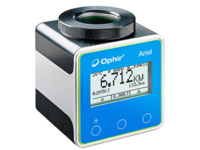
For the Ariel, we do not specify the “damage threshold” as such, and instead we give the table of recommended beam size and exposure time (near the bottom of the specifications page). This is the best way to define the operating parameters since the damage threshold is dependent on the exposure time for these types of measurements (where we are measuring powers that are much higher than what the sensor can measure in CW mode). So, the best way to avoid damage is to follow the specified guidelines for exposure times and beam sizes.

Calibration

05/26/15

The answer to this question is two-fold. First of all the recalibration process accomplishes the recalibration of the sensor and returns it to "as-new" working condition. If there is surface damage on the sensor disc that creates areas of non-uniformity exceeding the uniformity across-the-surface specification, then the disc needs to be replaced, even though the accuracy performance of the sensor is not out-of-tolerance. Secondly, many applications require that sensors be found in-tolerance during the calibration process, or else deviation explanations are required and/or costly recalls may need to be implemented. The calibration process is intended to help maintain the sensors within tolerance if at all possible.

03/06/16

Yes. Thermal sensors are calibrated at 532nm, 1064nm and 10.6µm. If (for example) only 1064nm, the fundamental YAG laser wavelength is used, then the other two laser wavelengths can be disabled and we will only recalibrate at 1064nm. This eliminates the potential for out-of-tolerance failures at the unused laser wavelength selections. If you put this request in the “Special Notes” section of the RMA request checklist form, we will then know to provide this option.

05/08/17

Our recalibration process is to not automatically upgrade the firmware in meters when they are sent in for recalibration, unless specifically requested to upgrade it. The reason for this is that we support many companies, such as medical companies, that have equipment validation processes that don’t allow changing the firmware version from the currently validated version. If you do want the latest firmware version installed, we will do that at no additional charge (for meters which are upgraded electronically) if it is specifically requested on the RMA request checklist form. For older meters (such as the Nova) that are upgraded through changing the EEPROM, a nominal fee is added, if firmware upgrade is requested. Note; upgrading the firmware does not affect the calibration.

06/09/14

The 3A-P actually absorbs about 85% at 10.6µm and therefore it can be used to measure weak CO2 lasers. Note the low power damage threshold, however, of 50W/cm2.

01/15/15

The RM9 is only sensitive to signals chopped at 18 Hz, so placing the chopper as close to the laser source as possible will minimize stray light entering the chopper and being read as part of the signal.
The noise specification is based on a 10 second moving average. Set the power meter to average the measurements for optimal performance.
It is also recommended to zero the sensor before use. This is done by disconnecting the BNC cable between the RM9 sensor and the chopper or turning off the chopper. Then follow the regular instructions for zeroing that can found in your power meter or PC interface manual.

Radiometer

08/26/20

Typical choppers have the same type of surface on both faces: either metallic, low emissivity or black, high emissivity.
When blocking the laser beam, metallic surfaces will reflect or scatter a significant portion of the laser power which may result in stray reflections reaching the sensor.
Black surfaces solve this issue, but if the chopper is positioned close to the RM9 or RM9-THz sensor, they will pick up a thermal signal from the chopper blades.
Stray reflections and thermal signal from the blades can impair measurement accuracy.
Our chopper enjoys the best of both worlds. It has a black surface that should face the laser beam and a low emissivity surface that should face the sensor.

Other Specs

01/01/17

Well, partly right.

Ophir has for many years had a few sensors that are designed for intermittent use. They are marked by two numbers like 50(150), which means it can measure 50 W continuously, or 150 W for a brief exposure (1.5 minutes in this example). Keeping in mind that power is energy over time, and that it is the total energy absorbed over time that causes a sensor to heat up, it should be possible to expose a sensor to “too high” power but only for a short time, and have the sensor survive the experience. The sensor can treat that short exposure as if it were just one long “single shot” pulse, and measure the energy of that pulse. Divide the energy by the (known) pulse width, and that gives the power during the pulse. (It can’t measure power directly this way, though, since a thermal sensor’s response time to power is itself a few seconds). For example, the moderate-power L40(250)A-LP2-50 has a 10KJ energy scale (several other sensors also have multi kJ scales); to measure power of an 8KW beam, we can fire the laser for 0.5 seconds with the sensor in energy mode, and we’ll measure 4KJ energy in the “pulse”. Dividing that by 0.5 seconds gives the 8KW beam power. Of course we then need to wait for the sensor to cool before repeating, but in some applications that may be perfectly OK
If you have a Juno, Juno+, Centauri or StarBright meter, you can do the above automatically, with any power sensor, using StarBright’s “Pulsed Power” function where you input the pulse duration and the meter will give the readout directly in power.

10/23/17

The new “LP2” type sensors are specially designed for beams having high power and high power density (and for pulsed beams, high energy density). The LP2 sensors are replacing the equivalent LP1 sensors; as impressive as the LP1 is, the LP2 was developed with the following improvements:

  • Very high damage threshold, for both power density and energy density, for long pulse and CW beams;
  • Spectrally flat; since its absorption remains constant at widely differing wavelengths, this means that sensors based on the LP2 can be used for "white light" or polychromatic beams;
  • Very high level of absorption (as high as 96%, depending on wavelength), meaning much less light is scattered back, which for high power beams is an important benefit;
  • The absorption is also largely independent of incident angle, which means it can be used for divergent beams too.
01/20/20

These sensors (e.g. 3A, 10A, 12A) are sensitive enough that even small air currents near the sensor can be picked up by them, and can result in some slow thermal drift in the reading. The “tube” (or “snout” as we sometimes call it) prevents this problem, or at least minimizes it, by reducing the degree to which air flow in the room becomes air flow near the sensor’s absorber surface, and also it limits the sensor’s solid angle “field of view”.

06/09/14

In general, the dynamic range over a given range, i.e. the ratio of maximum useable power to minimum useable power of Ophir thermal OEM sensors is 40:1. If greater dynamic range is desired, Ophir OEM RS232 sensors are available with several selectable ranges.

06/09/14

Yes. Please reference the chart below:

Minimum Flow Rates for Water-Cooled Sensors

Sensor Recommended flow rate at full power1 Minimum flow rate at full power1 Absolute minimum flow rate pressure drop across sensor (at maximum flow rate) pressure drop across 8 meter of tubing (at maximum flow rate)
liters/min) (liters/min) (liters/min) Bar MPa Bar MPa
L250W 3 3 3 0.3 0.03    
L300W 3 3 3 0.3 0.03    
1000W 6 3 3 0.3 0.03 0.5 0.05
L1500W 6 3.5 3 0.3 0.03 0.5 0.05
L2000W 6 3.5 3 0.6 0.06 0.5 0.05
5000W 8 5 3 0.6 0.06 0.5 0.05
6K-W-200x200 6 6 5 0.5 0.05 0.3 0.03
10K-W 8 8 3 1 0.1 0.5 0.05
15K-W 12 12 3 2 0.2 1 0.1
16K-W 12 12 3 1 0.1 0.8 0.08
30K-W 25 25 6 2 0.2 3 0.3
120K-W 60 60 30 4 0.4 3.5 0.035

You can find a lot more information about the correct use of water-cooled sensors in the article "How to use water cooled Ophir sensors", here.

07/17/14

Water cooled sensors will hardly be affected by ambient temperature since the sensor temperature is determined by the water temperature.
Ophir convection and fan cooled sensors are designed to operate in an ambient environment of 25degC up to the maximum rated power continuously.
When operating at its maximum rated power, the sensor’s body should typically not exceed about 80degC in temperature.
Note: If the room temperature is higher than 25degC, then the maximum power (at which the sensor can be safely operated) should be derated accordingly from the specified maximum (since dissipation of the heat from inside the sensor to the surrounding air will be more difficult). For example, if the room temperature is 35degC, then the maximum power limit should be (80-35)/(80-25) = 82% of maximum rated power as given in the sensor’s spec.

05/26/15

The energy threshold (at which a thermal head will be triggered to begin a single pulse energy measurement) has 3 levels: HIGH - ~3% of full scale; MED - ~1% of full scale and LOW - ~0.3% of full scale. Sometimes the lowest energy range and LOW level give false triggering or missing pulses. In any case the standard deviation will be relatively higher in the threshold area. If the head is used in stable conditions, it is generally possible to measure single shot pulses below the specified limit, though its value will be less accurate.

Using Your Sensor

11/07/16

Basic use with Profinet requires one power supply cable and one Profinet cable. Using RS232 or the PC application requires one power supply cable and one RS232 cable. If you want to use the Helios in a line/star topology, where it is daisy-chained with the next device in line, then you should use two power supply cables and two Profinet cables.
RS232 uses a standard DB9 RS232 cable. Profinet uses a Profinet-grade cable and RJ45 connectors. The power supply is a standard Profinet power supply from the Han PushPull series. For more information and mating connectors, see Chapter 3 of the manual.

11/07/16

This is limited by the temperature the Helios body reaches, that is measured by an internal sensor. The temperature shouldn’t be allowed to exceed 60° C. In our experience, this translates to about 40 kJ of accumulated exposure. Of course, the longer one waits in between pulses (allowing the body to cool), the more total energy it can take. That is why the temperature sensor should be used as the primary indicator of overheating, while 40 kJ should be treated as a rule of thumb.

05/26/15

Assuming the water temperature and flow rate are stable, the 2 possible concerns in such a case would be:

  • Water condensation on the absorbing surface
     
  • Offset caused by the difference between the ambient room temperature and the temperature of the sensor. The sensor "sees" 2 different temperatures – that of the cooling water flowing inside it, and that of the room air around it. If that temperature difference is small (as it usually is if the water temperature is in the usual specified range), then the air temperature's effect on the sensor body will be negligible compared with the cooling water temperature. However, if it is a large difference, there will be some level of heat flow between the (cold) sensor and the (warmer) air, and this will result in some level of offset in the reading.


You can find a lot more information about the correct use of water-cooled sensors in the article "How to use water cooled Ophir sensors", here.

11/07/16

There are seven LEDs for different status/error indications. From left to right (and top to bottom), the LEDs are:

  1. Power
  2. COM (Green)
  3. COM (Red)
  4. Link (Port 1)
  5. TX/RX (Port 1)
  6. Link (Port 2)
  7. TX/RX (Port 2)

For more detailed information, see Chapter 7 of the manual.

05/26/15

The required flow rate is proportional to the power, i.e. (min flow rate) = (published flow rate at max power)*(actual power input)/(rated maximum power) with the provision that the minimum flow rate should not be less than 1/4 of the published rate at full power.


You can find a lot more information about the correct use of water-cooled sensors in the article "How to use water cooled Ophir sensors", here.

05/26/15

Yes. The BB type thermal sensors will give the correct measurement as long as the wavelength selection is set to the wavelength of the light illumination source.

The measurement for broadband light will be the sum total of the radiation at all wavelengths above and below the wavelength set. However, the accuracy of the reading will depend on how much variation there is in absorption over the entire spectrum. The BB coating is quite flat spectrally (see graph below). In the spectral range of 500nm-1200nm, typical for IPL, the variation in absorption is only about 1.5. So, the accuracy of measuring the total energy will be good as long as you set the wavelength setting to the VIS or <800 selection (which is calibrated at 532nm).


Can I use a thermal BB (broadband) type sensor to measure an IPL source?

05/18/17

These sensors have a gold-coated reflecting cone, which can be easily scratched. If one of these sensors needs to be cleaned, we recommend blowing with clean air or nitrogen. If, however, the cone gets soiled (for example with something spilled on it), such that blowing is not enough to clean it, then there is a risk of the contaminant material getting “burned in” by laser radiation. In such a case, to avoid that risk, one should use a suitably soft tissue with solvent, and wipe as gently as possible.

03/06/16

Many factors affect the risk of corrosion forming, but the two most important are:

  • the mixture of ions in the water
  • the water’s pH

Our current recommendation is to use DI water – but of a neutral pH. DI water is usually slightly acidic; it can be titrated to a neutral pH, using a bit of sodium hydroxide for example. There are also commercial additives that can help prevent corrosion, for instance Optishield Plus. For a more detailed discussion, see the FAQ at https://www.ophiropt.com/laser--measurement/knowledge-center/faq/7805


You can find a lot more information about the correct use of water-cooled sensors in the article "How to use water cooled Ophir sensors", here.

05/02/16

Corrosion is caused by interactions between the metallic components of the sensor and the cooling water, which may contain a variety of dissolved ions. Many factors affect the risk of corrosion forming, but the most important are the pH and the mixture of ions in the water. For this reason, we recommend using neutral deionized water in a closed circulating system (pH between 6 and 8). Please note that deionized water is usually slightly acidic (pH 5.65) due to absorption of CO2 from the atmosphere. The cooling water can be neutralized by adding 5 ml of a 10 mM solution of NaOH for each liter of water in the cooling system. Commercial additives such as Optishield Plus are also recommended for systems such as ours that have copper and aluminum in them. Optishield has the additional benefit of having biocide to prevent buildup of organic contamination.

To prevent corrosion it is also crucial to not allow standing water to evaporate inside the sensor when it is not in use. When disconnecting a sensor from the cooling system, the water channel should be cleared by blowing compressed air through it.

For those customers still experiencing problems with corrosion, we recommend the new thermal sensor 1000WP-BB-34 which has a special design in which all materials that come into contact with the cooling water are either copper or nonmetallic.

You can find a lot more information about the correct use of water-cooled sensors in the article "How to use water cooled Ophir sensors", here.

06/09/14

Thermal sensors for intermittent use such as models 30(150)A, L40(250)A-BB-50 etc. can be used up to the powers in parenthesis for a period given approximately by the following formula: The rule of thumb is that you can use the sensor for 1 minute/watt/cm3 of sensor. So for 150 watts for 30(150)A you have 1minute*165cm3/150watt =~ a little over one minute. The sensor finder program calculates the allowability of intermittent use when the user fills out the choice for duty cycle.

06/09/16

This sensor must have water flowing, since the way it works is by measuring (a) the temperature difference between inflowing and outflowing water, and (b) the water flow rate. In other words, the water is part of the measurement mechanism. This is unlike regular water-cooled thermopile sensors, which use water only for cooling – and hence can get away without it in some cases if thermal conditions permit.

06/23/14

There are a number of options, depending on the purpose.

  • In many cases, the simplest solution could be to make use of the analog output of the meter – that gives a voltage signal proportional to the actual reading (it is in fact just a D/A translation of what is being displayed), so it represents a fully calibrated reading. The full scale value is a function of the meter being used and the power range it is on.
  • The "SH to BNC connector" (Ophir P/N 7Z11010) simply takes the raw output from the detector element and sends it to the scope. It bypasses the sensor's EEROM which contains the calibration data, so it essentially turns the sensor into an uncalibrated "dumb" analog sensor. It should be noted, though, that in some cases we could be talking about a signal to the scope that may be low, perhaps even near the noise level of the scope, which limits the usefulness of this method at low powers.
  • If the need is to see the pulse width – the temporal profile – the solution (assuming applicable specs) is to use an approprinte temporal sensor connected to a scope; you can point it anywhere where it will catch some backscatter from your laser, and you'll see the pulse temporal form as it really is.
10/28/19

In order to measure the fiber laser power we need to assure on one hand that the beam size on the absorber is not to small so as to exceed the power density requirements of the absorber and on the other hand that the beam size is not so large that it does not fit into the aperture. This necessitates two lengths of fiber adapter, the QBH-L & QBH-S
The QBH-L (P/N:7Z08348) is suited for beams with divergence angles of up to 120 mrad (for 86% of the beam), the minimum divergence angle depends on total power and the graph in the datasheet should be consulted for exact values.
The QBH-S (P/N:7Z08349) is suited for beams with divergence angles of up to 180 mrad (for 86% of the beam), the minimum divergence angle depends on total power and the graph in the datasheet should be consulted for exact values.
For more information please contact Ophir’s representatives.

01/15/15

It is fully compatible with these meters/interfaces:

  • Vega / Nova II (firmware vs. 2.44 or higher)
  • Juno (1.31 or higher)
  • StarLite (1.26 or higher)
  • StarBright (1.18 or higher)
  • Centauri
  • Juno+
  • EA-1

It is partially compatible with Ophir’s other meters (Nova, LaserStar, Pulsar, and Quasar). It will function properly with these devices, except with an upper power limit of ~1 mW instead of 100 mW and with reduced accuracy, see specs for more details.

10/28/19

For laser powers up to 1500W use the L1500W-LP2-50 (P/N: 7Z02772) sensor or the L1500W-BB-50 (P/N: 7Z02752) sensor.
For laser powers up to 5000W use the 5000W-LP2-50 (a) (P/N: 7Z02773) sensor or the 5000W-BB-50 (P/N: 7Z02754) sensor.
Note: (a) Please note that older versions of the above sensors do not have the requisite 4 threads on Ø70mm circle on their front flange and cannot be used with the QBH adapter

01/15/15

Yes, but keep in mind that the RM9 will measure average power, not energy. Also, pulse rates below ~50 Hz may generate additional noise. Pulse rates close to 18 Hz may cause beat frequency issues.

01/15/15

Yes, but it must be set to a chopping frequency of 18 Hz.
If your chopper has high emissivity (black) surfaces, it should be located as far from the sensor as possible, at least 200 to 300 mm.
If your chopper has low emissivity (bare metal) surfaces, care should be taken to ensure that when it blocks the laser beam it does not generate stray reflections that can reach the sensor

01/15/15

If your source happens to be pulsed at 18 Hz, you cannot use the chopper, since this will generate very low frequency beat signals. However, it might be possible to use the RM9 directly with your laser source, as long as you can connect a BNC sync to the RM9 sensor. Contact us about your particular application to be sure this is the right solution for you.

05/26/15

Water cooled sensors will not work properly at all unless the sensor is filled with water to make thermal contact between the disc and sensor. If the sensor is filled with water and the input and output connectors are stopped up, then the sensor can be used for a short time without water flow or at much reduced power continuously. Note, however, that when used this way, the reading will likely be incorrect by 5-10% and the response time of the sensor may not be optimal and it may be slow or overshoot.


You can find a lot more information about the correct use of water-cooled sensors in the article "How to use water cooled Ophir sensors", here.

11/13/19

If the setup and the water cooling are all stable (of course, that should be checked), there is no reason - as far as the sensor is concerned - that the reading should show significant fluctuations. A simple way to diagnose this: Try placing a photodiode in front of the sensor and facing towards it. It will sample a bit of the back-reflected power from the sensor; looking at the photodiode’s output signal will tell you if the fluctuations are real or not.

05/26/15

It is not necessary to cool it with water all the time. However, when the water is turned on, there is a transient period where the reading is not stable until the sensor adjusts to the water flow. Therefore, turn on the water before applying the laser and wait until you get a stable reading close to zero before applying the laser. This can take up to 1 minute.


You can find a lot more information about the correct use of water-cooled sensors in the article "How to use water cooled Ophir sensors", here.

08/18/21

The short answer: Yes. Now to explain: The question comes up because of the concern that the internal fast photodiode - which measures the exposure time (“pulse width”) - might get confused at sensing the end of an individual pulse within a pulsed beam, and incorrectly think that it has now measured the exposure time and needs to divide the measured energy by that time (which would of course be wrong). The Helios Plus is a bit smarter than that though; it looks simultaneously at the outputs from the fast photodiode AND from the (much slower) thermal sensor, and if it sees that the thermal sensor’s output has not “come back down”, then it knows what looked like the “end of the pulse” from the fast photodiode’s output is not really the end of the pulse.

05/26/15

The thermal sensor works by measuring the heat flowing through its sensor. When measuring a short pulse, the heat is absorbed in the sensor absorber and then flows out through the sensing elements. The integral of this heat flow is a measure of the energy. Thus the sensor is actually measuring the energy that flows after the pulse is finished and the pulse width does not matter for this measurement.