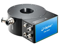
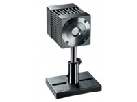
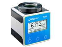
All Ophir pyroelectric sensors can measure average power with Ophir Power and Energy Meters. The instrument measures the number of pulses each second and multiplies the energy reading by the pulse rate. If the pulse rate is constant, then the accuracy of power measurement will be the same as the energy accuracy since the pulse rate measurement is very accurate.
Power Meters FAQ's
Accuracy
All PE sensors are less accurate at a low percentage of full scale. Therefore it is always recommended to measure energies on the lowest range available (e.g. measure 1.8mJ on the 2mJ scale not the 20mJ scale). In order to get highest accuracy from your sensor, especially at low percentage of full scale, it should be zeroed against the meter the first time it is used with this meter. This is especially true for the PE-C series that can be used down to 3% of full scale if zeroed but can have an error of 2% at 10% of scale if not. The sensors are factory zeroed against the Vega/Nova II so need not be rezeroed if used with these types. If used with the Juno, Pulsar, USBI or LaserStar, they should be rezeroed. If zeroed with one type and then later used with a different type, they should be rezeroed the first time used with the different type.
Ophir pyroelectric sensors have a positive temperature coefficient of 0.2% per degC which means that if the sensor heats up 10 degrees, the reading will be 2% high. The newer PE-C series of pyroelectric sensors have a temperature sensor inside and this dependence is compensated for in the software. The PD10 and PD10-pJ sensors use photodiode detectors so their temperature coefficient is the same as the PD300 sensors as listed on the PD300 pages of the Ophir catalog.
The sensor will stop integrating after the pulse width setting is reached and will lose part of the pulse. It will then read low. For instance if you try to measure a pulse width of 200us on a pulse width setting of 100us, the sensor will probably ready about 50% of the true energy.
If the pulse repetition rate is close to the maximum allowable rate for the chosen pulse width option, the first 0.5-1s of readings may read incorrectly low. This is only a problem for long pulse width settings (exceeding ~5ms).
Basically, as the pulse rate increases, the sensor has less and less time for its output signal from a given pulse to drop back to zero before the next pulse; this is a function of both the thermal and electrical time constants of the sensor. We have a number of “tricks” in the design to enable the sensor to work at much higher pulse rates than it otherwise would, but eventually a maximum pulse rate is reached above which the sensor’s response is no longer able to keep up; as it approaches that maximum pulse rate, the “additional error with frequency” begins to show up.
So, in theory, that additional error is negligible through most of the frequency range of the sensor, and becomes relevant from about 70-80% of the sensor’s maximum pulse rate and up.
In practice, this is not always the whole story; there are sometimes acoustic resonance effects in the crystal that cause “peaks” and “dips” in this frequency-related uncertainty, so the maximum specified “additional error with frequency” is not always necessarily at the maximum frequency. When we specify “additional error with frequency” as maximum +/- 1.5% to 25KHz, what we guarantee is no more than +/-1.5% at any point - not necessarily the end points.