What’s That Blue Light Coming Out of Your Mouth?

From time to time, our company is asked to provide assistance to researchers whose primary field of study is not lasers. In 2005 I began working with a medical researcher at a major medical school whose primary field of study is Dental Material Science. He tested various light sources to photo-cure restorative materials directly in the mouth of the patient.

Author:

Chuck Reagan, Southeast Sales Engineer, Ophir-Spiricon

This researcher worked with light sources that ranged from conventional, filtered quartz-tungsten-halogen and filtered plasma-arc lights, to high intensity violet, UV, and blue LEDs. There are a great variety of lights available on the market; many are hand-held and battery operated. Some of these lights use glass-fibered light guides, while others emit light from an LED either through a lens or through a protective clear or frosted plate.

Because of the differences in types of lights and light guides, there are great differences in uniformity of the beams emitted from the light source. This nonuniformity causes uneven curing of the resin or epoxy material, weakens that material, and shortens the life of the dental repair.

In the years since I assisted this researcher, new materials and light sources continue to enter the market that must be tested. I was recently asked to image a light guide emitting tip to see an LED's distribution of power. The LED had a cover glass over it and we were able to image inside of the housing to the light source.

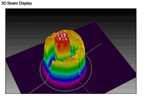
Using the BeamGage® Professional software and the Spiricon SP620 CCD camera with a Spiricon CCTV lens kit, we obtained the image below (Figure 1). It was exactly what the researcher needed. Using an Ophir power meter, the Vega, and an Ophir sensor, we obtained the power setting and entered that number into the BeamGage software. The software displayed optical power measurements and the beam size, which he needed for his experiment to be successful.

Figure 1. LED with glass cover.

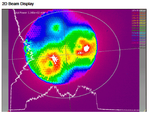
In the next example, we checked a different light guide. It was a three-diode, handheld battery operated light, which had two visible LED's and one UV LED combined into the same glass light guide. This light system had a cover glass over the glass fibers. We used the same lens system as before, but this time we used a frosted glass target as our imaging plane. In the two dimensional image below (Figure 2), we see the two visible LED's, but the UV LED is not strongly shown because my ND filters block light below 400nm and the UV LED is attenuated in this picture. Using band pass or notch filters, we can isolate each LED and obtain good results for each emitter at a later session. The camera is perfectly capable of imaging the UV as well as the visible LED's.

Figure 2. Two visible LED's and one UV LED in same glass guide.

In the final image below (Figure 3), we imaged directly into the light guide tip of the hand-held wand seen above and we did not use a frosted-glass image plane. The individual light fibers are visible below the cover glass, providing a bit more detail than the frosted glass examples from above.

Figure 3. Two visible LED's and one UV LED, no frosted-­‐glass.

Overall, the research team was very satisfied with the demonstration of the BeamGage camera and software. They are purchasing the system for future research projects.

Contact Us illustration

Have questions? Require assistance?

Click below to to contact Ophir Photonics and we'll get back with you shortly.

Contact Ophir Photonics