NanoScan Common causes of Damage to Scanheads & Reasons for Out-of-Tolerance Conditions

Problems you may encounter with a NanoScan scanning-slit beam profiler are due to either scanhead damage, or out-of-tolerance conditions.

Scanhead damage can be categorized into two main types; Laser and Mechanical. Laser damage is the most prevalent, and results from exposure to lasers with excessive laser power/energy density, and or high average power. The damage can be classified into 2 categories, designated "Instantaneous" and "Long-Term".

Slit Aperture Laser Cut Damage
Slit Aperture Laser Burn Damage

Instantaneous damage to slits occurs due to exposure to:

  • CW beams with Irradiance >~1x10⁶W/cm²
  • Pulsed beams with Fluence >~1J/cm²
  • Pulsed beams with Peak power >~1x10⁶W/cm²

Long-term exposure limits are given in units of time, and depend primarily on the beam average power and wavelength. Long-term heating raises the temperature of the slit and the drum due to exposure to CW or Pulsed beams with High Average Power in the range from approximately 10-100W.

Laser damage includes cut or distorted slits, damaged detectors, damaged power windows, warped optical encoder and circuit failure, and cut signal cables. Mechanical damage typically results from dropping the scanhead, "touching" the slit substrates, operation in high particulate environments, and repetitive motion.

Mechanical damage includes bent motor shafts, distorted slits, plugged slits, and broken signal cables.

Out-of-tolerance conditions are either system related, including problems associated with circuit or motor failure, or the scanhead is not appropriate for the application, such as using a Silicon detector to measure a 1550nm source, or a 25μm slit for a 10μm beam.

Descriptions of the various damage mechanisms and out-of-tolerance conditions, and guidelines to avoid such when possible are presented here.

A Nanoscan exposure limit calculator is available from the web under the Specification tab at: https://www.ophiropt.com/laser--measurement/beam-profilers/ products/Scanning-Slit-Beam-Profiling-with-NanoScan

Scanhead Damage - IMPORTANT WARNING!

Do not expose a NanoScan to a laser beam if the drum is not spinning! Scanhead damage thresholds are reduced below specifications when the drum is not spinning, increasing the possibility of damage to the scanhead.

High Power Caution

When measuring High Power CW or High Energy Pulsed lasers, do not expose a NanoScan to a laser beam if the drum is not spinning! The NanoScan drum does not spin unless the power is ON and the software is launched. The laser beams incident on the aperture may cause damage to the slits/pinholes and detector when the drum is NOT spinning. The slits/pinhole substrates are thin membranes which can be damaged if stopped in the beam, and if this occurs, the detector may also be damaged. Use of a beam dump is recommended until the drum is spinning!

When running long-term tests with NanoScan, Configure the PC Power Management to NEVER go off, and to NOT ALLOW Automatic Updates. These cause the computer to reboot, closing the NanoScan program and stopping the NanoScan drum, potentially subjecting it to the same type of damage.

Power Connection Caution

When unplugging the unit, NEVER unplug the unit without first turning off the software and closing the program. Likewise, when plugging in the unit, make certain that the program is not running. Failure to do so may result in the EEPROM being wiped, and the unit needing to be returned to Ophir-Spiricon for repair and recalibration.

Slit Damage Mechanical

Touching or contacting the slit substrates; for example, attempting to clean the slit with a cotton swab, or positioning a source such as an optical fiber, so that it contacts the slit substrate will damage the slits. Particle contamination results in plugged slits, and most likely is due to operation in a high particulate environment, or attempts to clean the slit.

NanoScan Aperture Care

The air slit and pinhole aperture substrates are very thin and extremely fragile. Any physical contact will likely damage them. Treat the slits with care; because of their fragility, never touch them with anything! Debris such as dust particle can loge in the very fine openings of the slits or pinholes and obstruct the passage of the incident beam, especially in the 1.8 μm slits. This can compromise instrument performance, resulting in erroneous or inconsistent measurements.

With slits, a few dust particles may or may not be a problem, depending on the application and measurement configuration, while contamination by many particles is more likely to create a problem. With pinhole apertures a single particle can be disastrous. Therefore, when the system is not is use, it is recommended that the protective plastic cap be used to cover the scanhead entrance aperture to avoid possible contamination. If inconsistent performance is observed and contamination by debris is suspected a clean jet of compressed gas may solve the problem, but excessive pressure may also damage the apertures. Do not under any circumstances attempt to clean the apertures with solvents!

If aperture contamination is suspected, it is recommended that the unit be returned to Ophir-Spiricon for aperture inspection, cleaning or replacement, and recalibration.

Laser

Laser damage to slits is caused by CW beams with excessive irradiance, pulsed beams with excessive peak irradiance, pulsed beams with excessive fluence, and long-term exposure to high average power CW or pulsed beams.

Consideration for CW Lasers: Irradiance

The irradiance of a CW laser is the power per unit area in W/cm², given by the power in Watts divided by the beam area in cm².

Consideration for Pulsed Lasers: Peak Irradiance and Fluence

The peak irradiance of a pulsed laser is given by the pulse energy in Joules divided by the beam area in cm2 and the pulse duration in seconds, usually taken as the FWHM width. The energy per pulse is the average power divided by the pulse frequency:

The fluence of a pulsed laser is the pulse energy per unit area, in units of Joules/cm2, given by the relation:

Slit Aperture "Instantaneous" Damage Thresholds

Damage thresholds are reported in NanoScan User Guide. Ophir-Spiricon does not warrant damage to slit apertures and detectors due to damage from high power lasers. Users of high-power lasers must exercise caution when measuring their laser beams with their NanoScan.

Slit apertures in NanoScan scanheads are made from a proprietary metallic alloy. The slit apertures are often blackened to reduce reflectivity and minimize reflections back into the laser cavity. Because of possible slit damage, Photon performed damage threshold tests on various NanoScan slit apertures to establish general use guidelines for prevention of damage to slit apertures. If you are concerned and still not sure, Photon can provide aperture material that you can use as a test before using your source on a NanoScan.

Blackened and unblackened apertures with 1.8μm, 5μm and 25μm nominal slit widths were tested. Tests were made at laser wavelengths of 532nm, 1.06μm, and 10.6μm. Damage thresholds are defined here to be the average laser irradiance at which the onset of visual damage occurs. The average irradiance is defined as the average power divided by the beam area at the 1/e² beam diameter.

All tests were performed under normal NanoScan operating conditions with the aperture slits moving. Damage to the slit apertures can occur at much lower power levels if the laser beam is directed into the slit apertures while the apertures are stationary.

The tests were performed at laser power levels <3 watts for short time exposures on the order of 5 minutes. The damage thresholds that were determined are therefore applicable only for short time exposures at these power levels. For high power lasers and long exposure times the damage thresholds are likely to decrease due to excessive heating of the apertures and/or possible ablation that does not manifest itself as visual damage in short term exposure tests. These effects have not yet been quantified, so users are advised to exercise extreme caution when attempting to measure high power beams for long time intervals. Long exposures may heat the entire NanoScan and cause other failures.

Note that for the case of blackened slit apertures, the onset of visual damage occurs when the black material begins to ablate. This type of damage should not affect the integrity of the slit but only the reflectivity of the aperture. However, this ablation of material may contribute to particulate contamination of the slits. Slit integrity is compromised at the higher laser irradiance associated with damage to unblackened apertures. This damage takes the forms of wrinkling or creasing of the aperture due to thermal stress and scoring of the aperture due to melting of the metallic alloy. At higher irradiance and longer exposure times the apertures can be cut. Recommended upper limits of average laser irradiance based on the results of the visual damage threshold tests for short time exposure (~5 minutes) at power levels less than 3 watts are summarized in Table 1. Values for 355nm were extrapolated from data at 532nm.

Table 1. Recommended maximum average laser irradiance incident on blackened and unblackened Nickel NanoScan slit apertures for short time exposures.

The values of average irradiance listed in the above table should be used as guidelines to determine if your operating conditions may cause damage to the apertures in your NanoScan scanhead for short time exposure at power levels <3W only. For long term exposures (>5 minutes) at higher power levels the damage thresholds may be reduced. Exercise Caution!

NanoScan Operating Space Charts

NanoScan Operating spaces for CW lasers include the appropriate damage thresholds for nickel and blackened nickel slit apertures. Figure 1 shows the Operating Space Chart for a NanoScan/Pyro/9/5; here there is only one damage threshold line for nickel slits because blackened slits are not available with pyro scanheads.

Figure 1. Operating Space Chart for the NanoScan/Pyro/9/5.

Refer to the NanoScan Installation and Operation manual for Operating Space Charts for all scanheads. Fluence exposure thresholds for pulsed lasers are given in Table 2 for nickel alloy, blackened nickel alloy and copper slit apertures.

Table 2. Recommended maximum fluence incident on blackened and unblackened Nickel, and copper NanoScan slit apertures for short time exposures.

These values are also shown in the Pulsed Damage Threshold curves given in figure 2. For pulsed lasers, specifically those in the picosecond and femtosecond regimes, it is very likely that the peak irradiance exceeds damage thresholds but the fluence per pulse is very low. In this case it is unlikely that instantaneous damage will occur, but long term damage from micromachining is likely. In this case, Proceed with Caution!

Figure 2. Pulsed Laser Damage Thresholds for nickel alloy and copper slit apertures

Long Term Slit Aperture Heating Exposure Limits

The long term exposure limits for slit aperture heating are based on a heating model where all the laser power goes into heating the slit aperture, and the time limit that is necessary to reach the melting point of the slit material, either nickel alloy or copper. When the slit heats the Instantaneous Damage thresholds decrease. The model provides conservative values for the time limit because it neglects thermal conduction into the drum. For reported times >5minutes, it is generally safe to operate with continuous exposure, but caution is advised. Exposure time limits for nickel alloy and copper slit apertures are given in Table 3.

Table 3. Slit Aperture Exposure Time Limits (minutes)

Long Term Drum Heating Exposure Limits

The long term exposure limits for drum heating are based on a heating model where all the laser power goes into heating the drum, and the time limit necessary to reach 100°C. The model provides conservative values for the time limit because it neglects convection cooling of the spinning drum. For reported times >5minutes, it is generally safe to operate with continuous exposure, but caution is advised. Exposure time limits for nickel alloy and copper slit apertures are given in table 4.

Table 4. Exposure Time Limits for Nickel Alloy and Copper Slit Apertures (minutes)

Power Window Damage (Laser)

Damage to the power window can occur at levels below the damage threshold for the slit aperture, specifically for the P75 Wratten Filter option, which has been discontinued as a product offering.

Power Window Damage

Detector Damage (Laser)

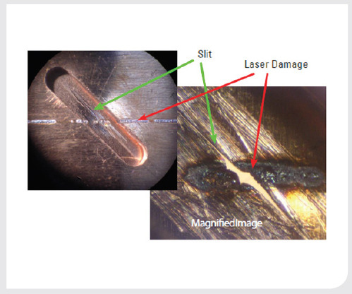
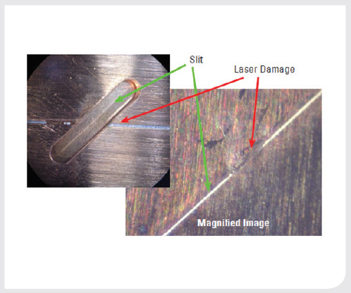
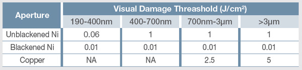
Detectors can be damaged if the slit aperture is cut or burned through and the detector is directly exposed. This damage is avoided by adhering to the guidelines for slit protection.

Circuit and Encoder Damage (Laser)

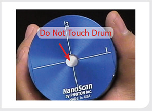
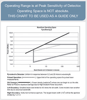
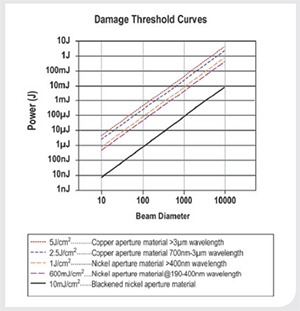
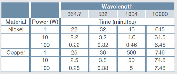
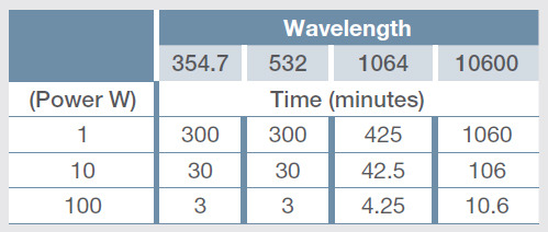
Failure of the NanoScan circuitry and the optical encoder can occur when the scanhead is exposed to high average power which causes the entire scanhead to heat. For example, exposure to 180Watts for only a minute or so can heat the drum to temperatures that cause warping of the encoder disc and catastrophic failure. This type of damage is avoided by using only short exposure times depending on the laser average power level. Safe operating time depends on the power as well as the slit material and laser wavelength. Table 4 gives safe operating times for different conditions.

Motor Damage (Mechanical)

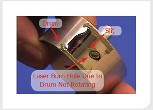
Typically motor damage is due to dropping the scanhead, which results in a bent motor shaft and consequent catastrophic failure. This type of damage can also occur during shipping if the scanhead is not packaged properly. To avoid this type of damage, do not drop the scanhead, and use at least 2" of rigid foam material or equivalent packaging if the system is shipped.

Cable (Mechanical)

The signal cable can be damaged due to bending the cable to too tight a radius, or from repetitive bending when the scanhead undergoes repetitive motion.

Cable (Laser)

The cable can be severed by a high power laser when accidentally exposed to high power/energy lasers. This type of damage is avoided by careful routing of the cable.

Out of Tolerance Conditions

Out-of-tolerance conditions are of two main types: either system related or use related.

specific application. Examples include using a Silicon detector to measure a 1550nm source, measuring a 10μm spot with a 25μm slit, or measuring 100μm spot at 1064nm with a Si detector. These conditions are remedied by the use of the proper scanhead, which should have been the one specified at the time of purchase. However, many times scanheads are then used in other situations, and that is where problems can arise.

System related problems include items such as ScanHead EEPROM Communication, Motor Quiescent Voltage, Motor Speed, and Baseline Offset Voltage. System related conditions are diagnosed in the software during system startup, and if encountered the system will not start and an error message is displayed. There is nothing that can be done for these conditions except returning the system for calibration.

Need Additional Help?

Here at Ophir-Spiricon we are committed to the satisfaction of our customers. If you would like to speak to a representative about any information contained in this article, about new products, or to optimize your laser measurement system for accurate, consistent, and highly repeatable results, please do not hesitate to contact us.

Contact Us illustration

Have questions? Require assistance?

Click below to to contact Ophir Photonics and we'll get back with you shortly.

Contact Ophir Photonics