Beam Width Measurement Methods in Beamwatch
A Review Of The D4σ (Moving Slit) And D4σ (Iterative) Methods
The high-power laser industry has seen tremendous growth in recent years. The use of different wavelengths and various beam shaping has allowed this technology to advance at an alarming pace. To meet the needs of the market demands, the noncontact measurement system in the BeamWatch family of products is also evolving.
This paper describes the measurement methods available in BeamWatch, demonstrates the accuracy, and provides guidance on how to select the proper measurement method for various configurations. The intent is to respond to questions surrounding the accuracy and capabilities of Rayleigh scatter beam profiling systems.
Authors:
Fon Brown, Rachael Callaway, Oleg Zinoviev
D4σ (Moving Slit)
The initial ISO-compliant beam width measurement incorporated into BeamWatch leveraged the 1/e² threshold-based method, a similar technique to the moving slit methodology as outlined in 11146-3:2004(E) Section 4.4. The details of this method are described in another paper1 which also compares data taken using the Rayleigh scatter methodology against camera and moving slit measurement techniques.
While the D4σ (Moving Slit) method is reliable for Gaussian and Top-Hat beams (even under noisy conditions) this technique tends to underestimate the waist diameter of specific non-Gaussian beams such as Donut or dual Ring/Core. As different beam structures become more widely incorporated in the industry, especially in welding and additive manufacturing applications, an alternate D4σ approach is needed.
D4σ (Iterative)
The D4σ (Iterative) beam width method uses a second moment approach to compute the width of each one-dimensional beam profile prior to computing the caustic. This method can provide better results for beam profiles that deviate from Gaussian. However, it can be more sensitive to noise, particularly for those profiles distant from the beam waist.
To address the higher sensitivity, a Region of Interest (ROI) is applied to ignore pixels beyond 6σ from the beam center, analogous to ISO 11146-1:2021(E) Section 7.2.
For BeamWatch, the width of the beam profile is computed after the effects of the camera's lens and aperture have been corrected. The initial estimate of σ and the initial ROI are computed using the 1/e² threshold method (ISO 11146-3:2004(E) Section 4.4 for moving slits), and for each iteration thereafter the algorithm:
- Computes a background correction
- Computes a new value for the first and second moments using the current ROI and corrected pixel intensities
- Recomputes a new σ and ROI based on the new moments.
The process is repeated until the ROI converges or until a maximum iteration count has been reached.
Background Correction
The background correction is assumed to be linear across the beam profile (Figure 1). It is performed in such a way that when the background correction is made, it minimizes the contribution to the second moment of the noise near the boundaries of the ROI.

It should be noted that errors may occur using this method if the beam is so large or off centered that the ±6σ ROI extends outside the visible frame. In such cases, this method may not be able to find a suitable background correction and may not have enough data points to compute accurate moments.
Background Correction
To verify the correct placement of the ROI, different beam types were modeled with varying widths and noise levels. Figure 2 shows representations of these beams. This analysis covered Signal to Noise (SNR) ratios from 10dB to 100dB.

After the ROI size and position were determined, the percentage of beam power contained within the ROI was computed. The results of this analysis are displayed in Table 1.
| Beam Width (Pixels) | |||||
| Beam Shape | 8 | 50 | 200 | 250 | 300 |
| Gaussian | 100.00% | 100.00% | 100.00% | 99.99% | 99.87% |
| Donut 100.00% | 100.00% | 100.00% | 100.00% | 99.93% | |
| Top-Hat | 100.00% | 100.00% | 100.00% | 100.00% | 100.00% |
| Ring/Core 99.94% | 100.00% | 100.00% | 100.00% | 99.86% | |
Each scenario contains over 99% of the beam power and is considered a good determination of the ROI. Notice that the percentage of power within the ROI starts to degrade as the beam width approaches the camera resolution limit of 512 pixels.
Measurement Comparisons
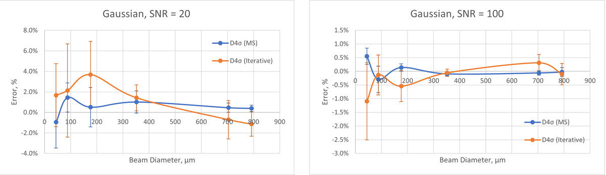
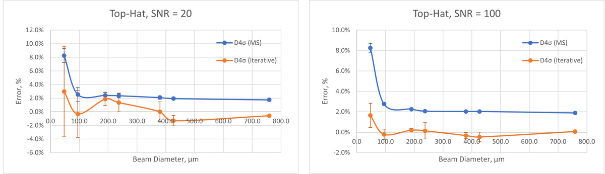
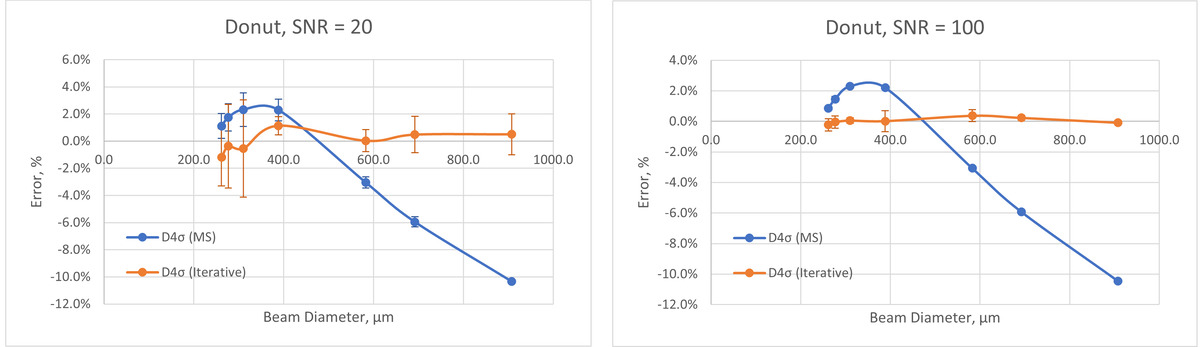
To compare the accuracy of the D4σ (Moving Slit) and the D4σ (Iterative) methods, multiple types of beam models were simulated with different profiles and beam widths. Noise was added and the profiles were blurred to simulate the BeamWatch optical system. The simulated data were then processed using the BeamWatch algorithms and results were compared against the initial beam parameters.
The images in the sections below present the systematic error and Beam Width repeatability error for Gaussian, Top-Hat, Donut, and Ring/Core beams. To display the most typical measurement scenarios, SNR values of both 20 and 100 were used.
Note: Studies shown here were performed on realworld data collected at customer sites using the BeamWatch device. However, to maintain supplier/user confidentiality, this report is based on simulated data which shows a high degree of correlation with the realworld data.
Gaussian
Top-Hat
Donut
Core/Ring
The Ring/Core beams have been studied as a percentage of total power contained within the Core. When the Core is
at 0% power, the beam is a Donut. Conversely, when the Core is at 100% power, the beam is Gaussian or Top-Hat.

Waist Location
The beam width measurement method can cause variation in the waist location. The definition of the D4σ (Iterative) approach creates a symmetrical caustic before and after the beam focus, while the D4σ (Moving Slit) allows the caustic to be asymmetrical.
More accurate waist location results are produced when the caustic is symmetrical and therefore the D4σ (Iterative) method is more appropriate when studying the waist location and focal shift results.
Conclusions
While the D4σ (Iterative) method has many accuracy and repeatability advantages, it also has some drawbacks. The ROI placement degrades as the background noise increases. Elevated levels of noise can cause an inability to calculate a caustic fit. Large beams, particularly for profiles away from the waist, may also see a degradation in accuracy as the ±6σ width approaches the camera resolution limits. The iterative ROI process also takes extra processing time which slows down the measurement rate.
A given measurement scenario will determine which method produces the most accurate results.
- D4σ (Iterative) may be effective when:
- The beam significantly departs from a typical Gaussian or Top-Hat distribution
- The image has high SNR
- The waist location and focal shift results are important
- D4σ (Moving Slit) may be effective when:
- The beam is close to Gaussian or Top-Hat distribution
- The image has high background noise
- The beam diameter is large
The D4σ (Moving Slit) and D4σ (Iterative) beam width methods are both viable measurement techniques. Each method conforms to their respective sections in the ISO standard and therefore produce the ISO labels in the BeamWatch application when sufficient Rayleigh Lengths are visible. Users can now obtain accurate measurements for a wider range of beams and measurement conditions using the BeamWatch.